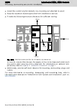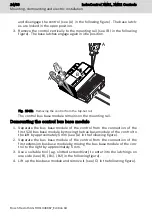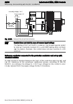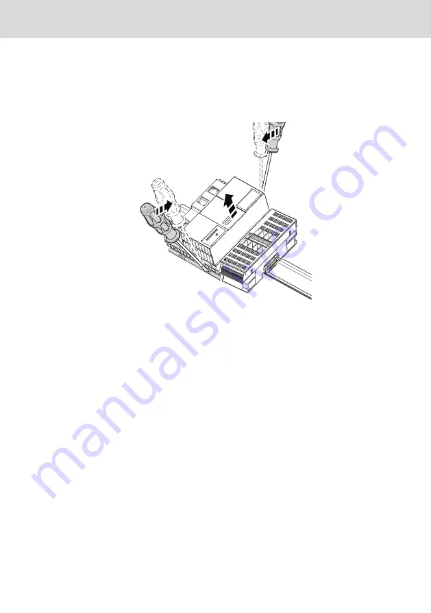
and disengage the control (see (A) in the following figure). The base latch-
es are locked in the open position.
3. Remove the control vertically to the mounting rail (see (B) in the following
figure). The base latches engage again in idle position.
B
A
A
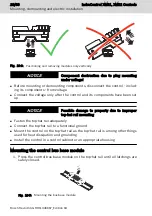
Fig. 10-12: Removing the control from the top-hat rail
The control bus base module remains on the mounting rail.
Demounting the control bus base module
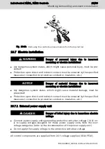
1. Separate the bus base module of the control from the connection of the
first S20 bus base module by moving the bus base module of the control to
the left by approximately 5 mm (see (A) in the following figure).
2. Separate the bus base module of the control from the connection of the
first extension bus base module by moving the bus base module of the con-
trol to the right by approximately 5 mm.
3. Use a suitable tool (e.g. slotted screwdriver) to enter into the latchings on
one side (see (B), (B1), (B2) in the following figure).
4. Lift up the bus base module and remove it (see (C) in the following figure).
24/69
Mounting, demounting and electric installation
IndraControl XM21, XM22 Controls
Bosch Rexroth AG R911340667_Edition 04
Summary of Contents for Rexroth IndraControl XM21
Page 1: ...IndraControl XM21 XM22 Controls Operating Instructions R911340667 Edition 04 ...
Page 6: ...IV IndraControl XM21 XM22 Controls Bosch Rexroth AG R911340667_Edition 04 ...
Page 70: ...64 69 IndraControl XM21 XM22 Controls Bosch Rexroth AG R911340667_Edition 04 ...
Page 73: ...IndraControl XM21 XM22 Controls 67 69 R911340667_Edition 04 Bosch Rexroth AG ...
Page 74: ...68 69 IndraControl XM21 XM22 Controls Bosch Rexroth AG R911340667_Edition 04 ...

