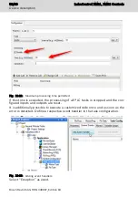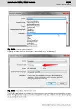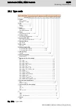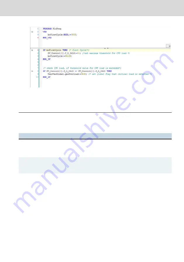
Fig. 12-24: Initialization and cyclic monitoring of the CPU load
This program section has to be called cyclically. Once the value "TRUE" was de-
tected for the variable "gboOverload", the PLC user program should respond ac-
cordingly, e.g. by switching off program parts or executing a minimal program.
13 Error causes and troubleshooting
The following table describes the LEDs on the power connector.
LED
LED display
Error causes and troubleshooting
U
L
LED is off
24 V voltage error
24 V supply voltage is not connected
24 V supply voltage is connected with reverse polarity
ON
LED is off
Error when loading the programmable logic
Initiate fallback mode (see
chapter 12.5 "Fallback and recovery" on
)
T
LED is red
Temperature error
Control was switched off due to overheating.
●
Ensure a lower ambient temperature
●
Check the control installation
●
Avoid heat accumulation impeding the natural convection
Tab. 13-1: LEDs in the voltage power connector
Further operating displays and error displays are located on the individual mod-
ules and terminals. For information on the other displays, refer to the manual of
the IndraControl S20 component (see also
chapter 1.3 "Related documents" on
).
IndraControl XM21, XM22 Controls
59/69
Error causes and troubleshooting
R911340667_Edition 04 Bosch Rexroth AG
Summary of Contents for Rexroth IndraControl XM21
Page 1: ...IndraControl XM21 XM22 Controls Operating Instructions R911340667 Edition 04 ...
Page 6: ...IV IndraControl XM21 XM22 Controls Bosch Rexroth AG R911340667_Edition 04 ...
Page 70: ...64 69 IndraControl XM21 XM22 Controls Bosch Rexroth AG R911340667_Edition 04 ...
Page 73: ...IndraControl XM21 XM22 Controls 67 69 R911340667_Edition 04 Bosch Rexroth AG ...
Page 74: ...68 69 IndraControl XM21 XM22 Controls Bosch Rexroth AG R911340667_Edition 04 ...

