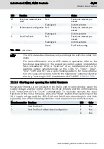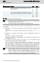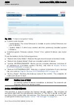
If it is not booted in this sequence, an error is present (see
13 "Error causes and troubleshooting" on page 59
12.5 Fallback and recovery
The hardware is initialized after switching on the control and after installing the
system firmware with subsequent reboot. Internally programmable function
blocks are loaded. These also include internally programmed function blocks of
connected modules. After the loading, the display LED "ON" at the voltage plug
is green.
Wait till completion. Do not switch off the control. This procedure has to be
completed.
If this display LED "ON" is not green, loading for internally programmed func-
tions block of an extension module or of the control failed. The display LED "ON"
of the control is a collective display for all connected modules and the control.
In this case, trigger the "Fallback mode":
1. Switch off the 24 V voltage supply for the XM2x control and the extension
modules.
2. Keep the “Reset” pushbutton "SF2" at the XM2x control pressed and
switch on the 24 V voltage supply. If either the display LED DIA3 or the LED
DIA4 is on at the XM2x control, release the “Reset” button "SF2".
If the display LED "ON" at the control XM2x is on, the error is eliminated.
If the display LED "ON" at the control XM2x is not on, initiate the "Fallback
mode" for the extension modules, whose display LED "ON" is not on.
3. Keep the “Fallback” pushbutton of the respective module pressed using a
plastic pen until the display LED "ON" is on at the extension module. This
loads a backup data set. Release the “Fallback” pushbutton. Perform this
step subsequently for all extension modules. First at those, whose display
LED "ON" was not on. After completing that for all extension modules, the
display LED "ON" of the XM2x control has to be on.
The XM2x control can only start if all connected extension modules
started without any errors. If the LED "ON" of a connected extension
module is not green, initiate the “Fallback” mode for this extension
module.
12.6 Backing up remanent data
128 KB of remanent data is automatically backed up in an internal flash memory
after a 24 V supply voltage failure and restored at control startup.
12.7 Real-time clock
The real-time clock of the control is buffered in the switched-off state. The buf-
fer capacitor looses efficiency when operated permanently at high tempera-
54/69
Device description
IndraControl XM21, XM22 Controls
Bosch Rexroth AG R911340667_Edition 04
Summary of Contents for Rexroth IndraControl XM21
Page 1: ...IndraControl XM21 XM22 Controls Operating Instructions R911340667 Edition 04 ...
Page 6: ...IV IndraControl XM21 XM22 Controls Bosch Rexroth AG R911340667_Edition 04 ...
Page 70: ...64 69 IndraControl XM21 XM22 Controls Bosch Rexroth AG R911340667_Edition 04 ...
Page 73: ...IndraControl XM21 XM22 Controls 67 69 R911340667_Edition 04 Bosch Rexroth AG ...
Page 74: ...68 69 IndraControl XM21 XM22 Controls Bosch Rexroth AG R911340667_Edition 04 ...


