Rexroth IndraDrive
Electrical Installation
7-11
DOK-INDRV*-HMV-*******-PR01-EN-P
7.5
Connecting Cables and Rails
Connections (Power Section)
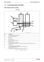
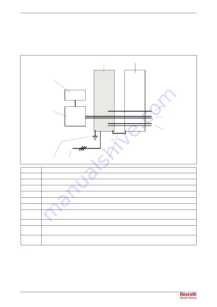
Overview
installation_hmv_system.fh7
2
3
A
B
C
D
4
5
6
1
No.
Designation
A
UPS (uninterruptible power system)
B
24 V control voltage supply
C
Supply unit
D
Drive controller
1
PE connection of mains supply
2
Mains connection
3
PE connection to drive controller;
If cables are used for ground connection they must have a cross section of at least 10 mm
2
.
4
Module bus X1
5
Control voltage connection (+24V, 0V);
If connection with contact isn’t possible you can also use wires.
6
DC bus connection (L+, L-);
If connection with contact isn’t possible you can also use wires.
Fig. 7-7:
Connections - overview
Summary of Contents for Rexroth IndraDrive HMV01.1E-W0030
Page 30: ...5 2 Transport and Storage Rexroth IndraDrive DOK INDRV HMV PR01 EN P Notes ...
Page 40: ...6 10 Mechanical Mounting Rexroth IndraDrive DOK INDRV HMV PR01 EN P Notes ...
Page 88: ...9 8 Control Mains Contactor Rexroth IndraDrive DOK INDRV HMV PR01 EN P Notes ...
Page 122: ...13 22 Appendix Rexroth IndraDrive DOK INDRV HMV PR01 EN P Fig 13 25 HFD01 2 480 0026 ...
Page 123: ...Rexroth IndraDrive Appendix 13 23 DOK INDRV HMV PR01 EN P Fig 13 26 HFD02 2 480 0026 ...
Page 130: ...14 6 Index Rexroth IndraDrive DOK INDRV HMV PR01 EN P Notes ...
Page 131: ......

