13-12
Appendix
Rexroth IndraDrive
DOK-INDRV*-HMV-*******-PR01-EN-P
Synchronizing to the Mains
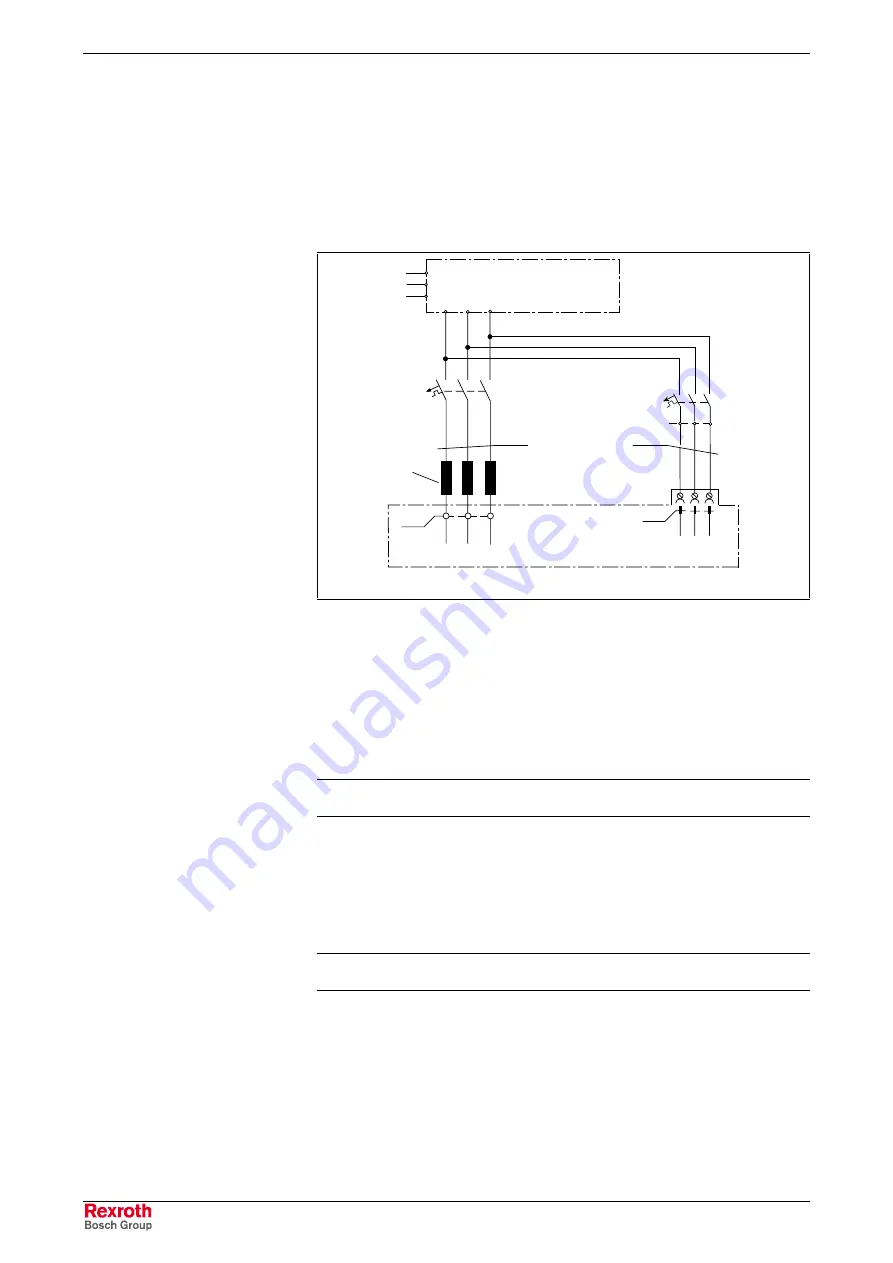
A separate connection is necessary that the HMV01.1R may be operated
synchronously to the mains. The synchronizing voltage must be tapped
before the mains choke KDxx but after the mains filter. Power and
synchronizing voltage connection must be in phase (see figure below).
The synchronizing voltage must be connected to the control voltage inlet
(X14) of the HMV01.1R.
X3
L1
L2
L3
X14
Q1
1
2
3
HMV01.1R
connection must be
phase coincident
Combining filter HFD
L1.1
KDxx
HMVR_Netzsynch_anschluss.FH7
F2
1)
L2.1 L3.1
L1
L2
L3
1)
Use a motor circuit-breaker (F2; e.g. PKZM6.3) or fuses (6.3 A) to
protect X14.
Fig. 13-12:
Synchronizing voltage HMV01.1R
Details of the Mains Choke
The mains chokes are equipped with a temperature contact which opens
at T = 150 °C (connections a - b). The contact can be evaluated by a
controller and is used for example for a regulated shutdown of the unit,
should the control cabinet cooling fail.
Note:
Technical data of mains chokes: see page 13-17
.
Details of the Combining Filter
When operating combining filters at grounded IT mains, the type of
construction causes leakage currents that may cause possibly existing
circuit breakers or voltage monitors to trip. Remedy: Install an isolating
transformer.
Note:
Technical data of HFD filters: see page 13-19
.
Summary of Contents for Rexroth IndraDrive HMV01.1E-W0030
Page 30: ...5 2 Transport and Storage Rexroth IndraDrive DOK INDRV HMV PR01 EN P Notes ...
Page 40: ...6 10 Mechanical Mounting Rexroth IndraDrive DOK INDRV HMV PR01 EN P Notes ...
Page 88: ...9 8 Control Mains Contactor Rexroth IndraDrive DOK INDRV HMV PR01 EN P Notes ...
Page 122: ...13 22 Appendix Rexroth IndraDrive DOK INDRV HMV PR01 EN P Fig 13 25 HFD01 2 480 0026 ...
Page 123: ...Rexroth IndraDrive Appendix 13 23 DOK INDRV HMV PR01 EN P Fig 13 26 HFD02 2 480 0026 ...
Page 130: ...14 6 Index Rexroth IndraDrive DOK INDRV HMV PR01 EN P Notes ...
Page 131: ......


