Rexroth IndraDrive
Mechanical Mounting
6-5
DOK-INDRV*-HMV-*******-PR01-EN-P
Installation Orientation
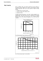
Install supply units in such a way that their longitudinal axis corresponds
to the natural direction of convection (connections for motor and power
downwards).
In this way the natural convection supports the forced cooling air current.
This avoids the generation of pockets of heat.
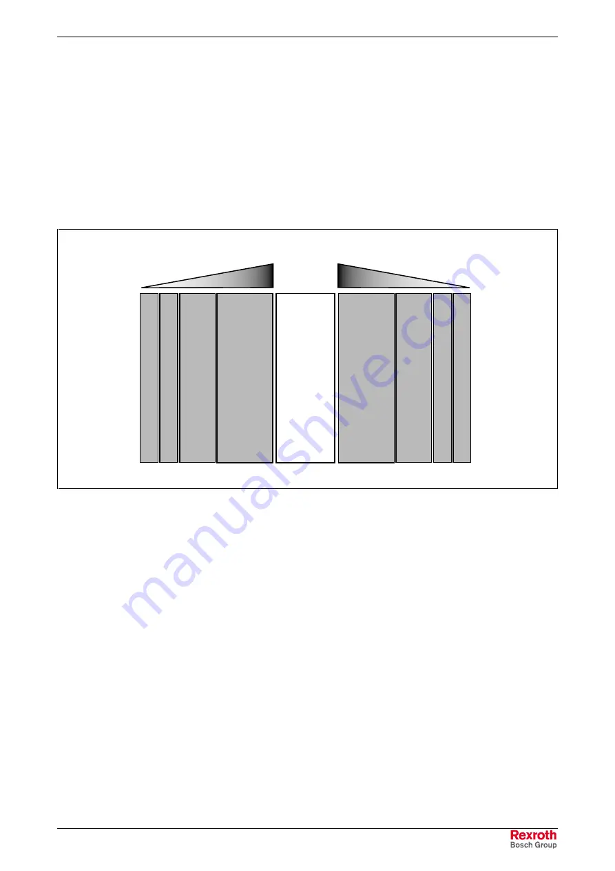
Arrangement of Components in the Control Cabinet
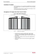
Power-dependent Arrangement
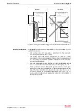
versorg_antrieb_sym.FH7
supply unit
drive controllers
high power
low power
high power
low power
drive controllers
Fig. 6-7:
Example of an arrangement
•
Arrange the drive controllers with higher power needs and high
currents as close to the supply unit as possible. Ideally the drive
controllers should be distributed equally to the left and right side of the
power supply.
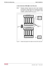
•
Position DC bus capacitor unit next to drive with the greatest DC bus
continuous output.
•
Position DC bus resistor unit next to drive with the greatest negative
feed power.
Summary of Contents for Rexroth IndraDrive HMV01.1E-W0030
Page 30: ...5 2 Transport and Storage Rexroth IndraDrive DOK INDRV HMV PR01 EN P Notes ...
Page 40: ...6 10 Mechanical Mounting Rexroth IndraDrive DOK INDRV HMV PR01 EN P Notes ...
Page 88: ...9 8 Control Mains Contactor Rexroth IndraDrive DOK INDRV HMV PR01 EN P Notes ...
Page 122: ...13 22 Appendix Rexroth IndraDrive DOK INDRV HMV PR01 EN P Fig 13 25 HFD01 2 480 0026 ...
Page 123: ...Rexroth IndraDrive Appendix 13 23 DOK INDRV HMV PR01 EN P Fig 13 26 HFD02 2 480 0026 ...
Page 130: ...14 6 Index Rexroth IndraDrive DOK INDRV HMV PR01 EN P Notes ...
Page 131: ......


