7-10
Electrical Installation
Rexroth IndraDrive
DOK-INDRV*-HMV-*******-PR01-EN-P
7.4
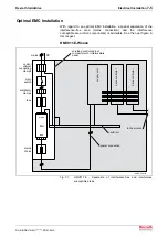
Complete Connection Diagram
L1
L2
L3
anschlussplan_hmv.FH7
RS232
acknowledgment power ON
acknowledgment power OFF
24V for interface
DC bus short circuit 24V
mains OFF
mains ON
0V for interface
ready for operation
DC bus ok
prewarning temp./bleeder
mains connection
module bus
mains contactor
ON
mains contactor
OFF
24V
0V
L+
L-
HMV 01.1x - Wxxxx
X3
24V control voltage
DC bus
mains connection
for synchronization
braking resistor threshold
fixed/variable **
PE
PE
4
3
2
1
9
8
7
6
5
4
3
2
1
6
5
4
3
2
1
8
7
6
5
4
3
2
1
8
7
6
5
4
3
2
1
3
2
1
X33
X32
X31
X2
X1
* only for HMV01.1R-Wxxxx
X14*
** only for HMV01.1E-Wxxxx
Fig. 7-6:
Complete connection diagram
Summary of Contents for Rexroth IndraDrive HMV01.1E-W0030
Page 30: ...5 2 Transport and Storage Rexroth IndraDrive DOK INDRV HMV PR01 EN P Notes ...
Page 40: ...6 10 Mechanical Mounting Rexroth IndraDrive DOK INDRV HMV PR01 EN P Notes ...
Page 88: ...9 8 Control Mains Contactor Rexroth IndraDrive DOK INDRV HMV PR01 EN P Notes ...
Page 122: ...13 22 Appendix Rexroth IndraDrive DOK INDRV HMV PR01 EN P Fig 13 25 HFD01 2 480 0026 ...
Page 123: ...Rexroth IndraDrive Appendix 13 23 DOK INDRV HMV PR01 EN P Fig 13 26 HFD02 2 480 0026 ...
Page 130: ...14 6 Index Rexroth IndraDrive DOK INDRV HMV PR01 EN P Notes ...
Page 131: ......

