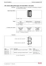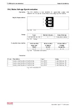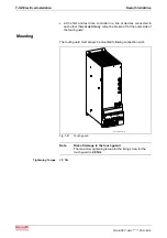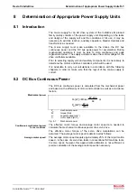
Rexroth IndraDrive
Determination of Appropriate Power Supply Units
8-7
DOK-INDRV*-HMV-*******-PR01-EN-P
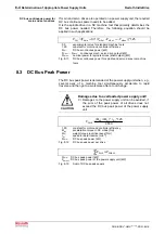
z
*
h
*
g
*
m
W
pot
=
W
pot
:
potential energy [Ws]
m:
load mass [kg]
g:
gravity constant = 9,81 m/s²
h:
drop height [m]
z:
number of drops per cycle
Fig. 8-20:
Potential energy of non-compensated masses
z
rotg
potg
RD
t
W
W
P
+
=
BD
RD
P
P
≤
P
RD
:
continuous regenerated power [kW]
P
BD
:
continuous bleeder power [kW]
t
z
:
cycle time [s]
W
potg
:
sum of potential energy [kWs]
W
rotg
:
sum of rotary energies [kWs]
Fig. 8-21:
Continuous regenerated energy
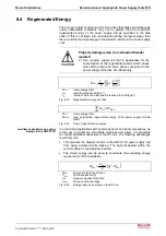
8.6
Peak Regenerated Power
The peak regenerated power usually arises, when an Emergency Stop
signal has been released and all the axes brake simultaneously.
CAUTION
Property damages due to longer braking
periods/paths!
⇒
Choose the power supply unit such that the sum of
the peak regenerated power of the all drives does not
exceed the bleeder peak power of the power supply
unit.
The peak regenerated power of the servo drives is listed in the motor
selection documentation.
Roughly estimated, the peak regenerated power can be calculated as
follows:
25
,
1
*
9550
n
*
M
P
max
max
RS
=
∑
≤
BS
Rs
P
P
P
RS
:
peak regenerated power [kW]
P
BS
:
peak bleeder power [kW]
M
max
:
max. drive torque [Nm]
n
max
:
max. NC usable speed [min
-1
]
1,25:
constant for motor and controller efficiency
Fig. 8-22:
Peak regenerated power
Summary of Contents for Rexroth IndraDrive HMV01.1E-W0030
Page 30: ...5 2 Transport and Storage Rexroth IndraDrive DOK INDRV HMV PR01 EN P Notes ...
Page 40: ...6 10 Mechanical Mounting Rexroth IndraDrive DOK INDRV HMV PR01 EN P Notes ...
Page 88: ...9 8 Control Mains Contactor Rexroth IndraDrive DOK INDRV HMV PR01 EN P Notes ...
Page 122: ...13 22 Appendix Rexroth IndraDrive DOK INDRV HMV PR01 EN P Fig 13 25 HFD01 2 480 0026 ...
Page 123: ...Rexroth IndraDrive Appendix 13 23 DOK INDRV HMV PR01 EN P Fig 13 26 HFD02 2 480 0026 ...
Page 130: ...14 6 Index Rexroth IndraDrive DOK INDRV HMV PR01 EN P Notes ...
Page 131: ......


