8-8
Determination of Appropriate Power Supply Units
Rexroth IndraDrive
DOK-INDRV*-HMV-*******-PR01-EN-P
8.7
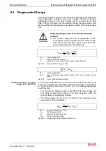
Connected Load of the Supply Unit
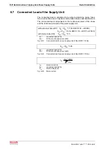
The connected load is calculated to be able to determine mains fuses,
line cross sections and, if needed, commutation chokes and transformers.
The connected load is dependent on the continuous power of the drives
and the functional principle of the power supply unit.
15
,
1
*
P
S
:
(KD)
choke
mains
with
)
0120
W
,
0075
W
E
1
.
01
HMV
for
(
5
,
1
*
P
S
)
0030
W
E
1
.
01
HMV
for
(
7
,
1
*
P
S
:
(KD)
choke
mains
without
ZW
1
N
ZW
1
N
ZW
1
N
=
−
−
=
−
=
S
N1
:
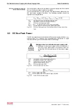
connected load [kVA]
P
ZW
:
DC bus continuous power [kW]
Fig. 8-23:
Connected load for power supply units of the HMV01.1E line
05
,
1
*
P
S
ZW
1
N
=
S
N1
:
connected load [kVA]
P
ZW
:
DC bus continuous power [kW]
Fig. 8-24:
Connected load for power supply units of the HMV01.1R line
1
N
1
N
1
N
U
*
3
1000
*
S
I
=
I
N1
:
mains current [I]
S
N1
:
connected load [kVA]
U
N1
:
mains voltage [U]
Fig. 8-25:
Mains current
Summary of Contents for Rexroth IndraDrive HMV01.1E-W0030
Page 30: ...5 2 Transport and Storage Rexroth IndraDrive DOK INDRV HMV PR01 EN P Notes ...
Page 40: ...6 10 Mechanical Mounting Rexroth IndraDrive DOK INDRV HMV PR01 EN P Notes ...
Page 88: ...9 8 Control Mains Contactor Rexroth IndraDrive DOK INDRV HMV PR01 EN P Notes ...
Page 122: ...13 22 Appendix Rexroth IndraDrive DOK INDRV HMV PR01 EN P Fig 13 25 HFD01 2 480 0026 ...
Page 123: ...Rexroth IndraDrive Appendix 13 23 DOK INDRV HMV PR01 EN P Fig 13 26 HFD02 2 480 0026 ...
Page 130: ...14 6 Index Rexroth IndraDrive DOK INDRV HMV PR01 EN P Notes ...
Page 131: ......


