4
Instructions for use
4.1
Mounting
Notes on mounting
1.
To allow trouble-free servicing, make sure that the following aspects are
fulfilled after KSM has been mounted:
●
Connection points are easily accessible
●
Address selector switches are easily accessible
●
Diagnostic LED is visible
2.
Preferably mount the device to a conductive surface. If this is impossi‐
ble, later on connect the second connection point of equipment ground‐
ing conductor at the device to the equipment grounding system of the in‐
stallation.
3.
For devices of the "W" and "A" cooling types, only the mounting position
G1 is allowed.
Mounting position G1: The air heated inside the component can flow un‐
impeded vertically upward. In the case of components with integrated
fans, the natural convection supports the forced cooling air current.
4.
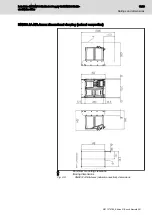
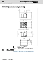
For the dimensions of the mounting holes, see the dimensional drawing
of the device.
5.
Data of the mounting screws:
Devices of "B" or "I" cooling type:
●
Thread: M5
●
Tightening torque: 6.1 Nm
Devices of "A" or "W" cooling type:
●
Thread: M6
●
Tightening torque: 10.4 Nm
Cold plate
Devices of cooling type "B" are mounted on a cold plate.
Required cold plate properties:
See
chapter 4.2 "Cold plate" on page 17
4.2
Cold plate
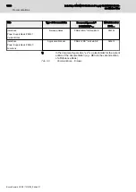
Required cold plate properties:
Description
Unit
Value
Surface temperature
°C
≤ 60
Flatness
mm
≤ 0.1
Surface roughness
-
Rz 6.3
Tab. 4-1:
Cold plate
IndraDrive Mi KMV03 Distributed Supply Unit KNK03 Distrib‐
uted Mains Filter
17/29
Instructions for use
R911374765_Edition 01 Bosch Rexroth AG


