1-16
Basics on Device Diagnosis
Rexroth IndraDrive
DOK-INDRV*-GEN-**VRS**-WA01-EN-P
Notes on Commissioning
CAUTION
Property damage caused by command-
dependent activation of motors and moving
elements!
⇒
Bring axis resp. moving parts in safe initial position;
limit travel range and drive power!
Note:
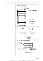
By pressing the "Esc" button again the standard display will
reappear.
Note:
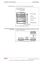
The input via the buttons is polled in an 8 ms-cycle, the display
is updated in an 8 ms-cycle, too.
1.3
Extended Diagnostic Possibilities
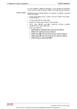
The firmware provides further possibilities of diagnosis. For the
description please see the Functional Description of the Firmware.
1.4
Kinds of Diagnostic Messages
Error
Depending on the operating mode that is used and some parameter
settings, the drive controller carries out monitoring functions. An error
message is generated by the drive controller, if a status is detected that
no longer allows correct operation.
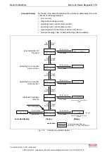
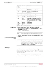
Errors can be divided into several error classes. The error class is
represented by the first two digits of the diagnostic message number.
If the drive controller is in control (drive enable was set) and an error
occurs, the drive controller automatically starts a drive error reaction.
The reaction to errors of certain classes can be influenced by the
P-0-0119, Best possible deceleration
parameter.
At the end of each error reaction, the drive is torque-free.
Error Classes
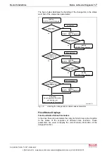
Drive Error Reaction
LSA Control S.L. www.lsa-control.com comercial@lsa-control.com (+34) 960 62 43 01

