Rexroth IndraDyn A
Type Codes IndraDyn A
6-3
DOK-MOTOR*-MAD/MAF****-PR03-EN-P
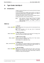
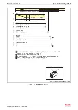
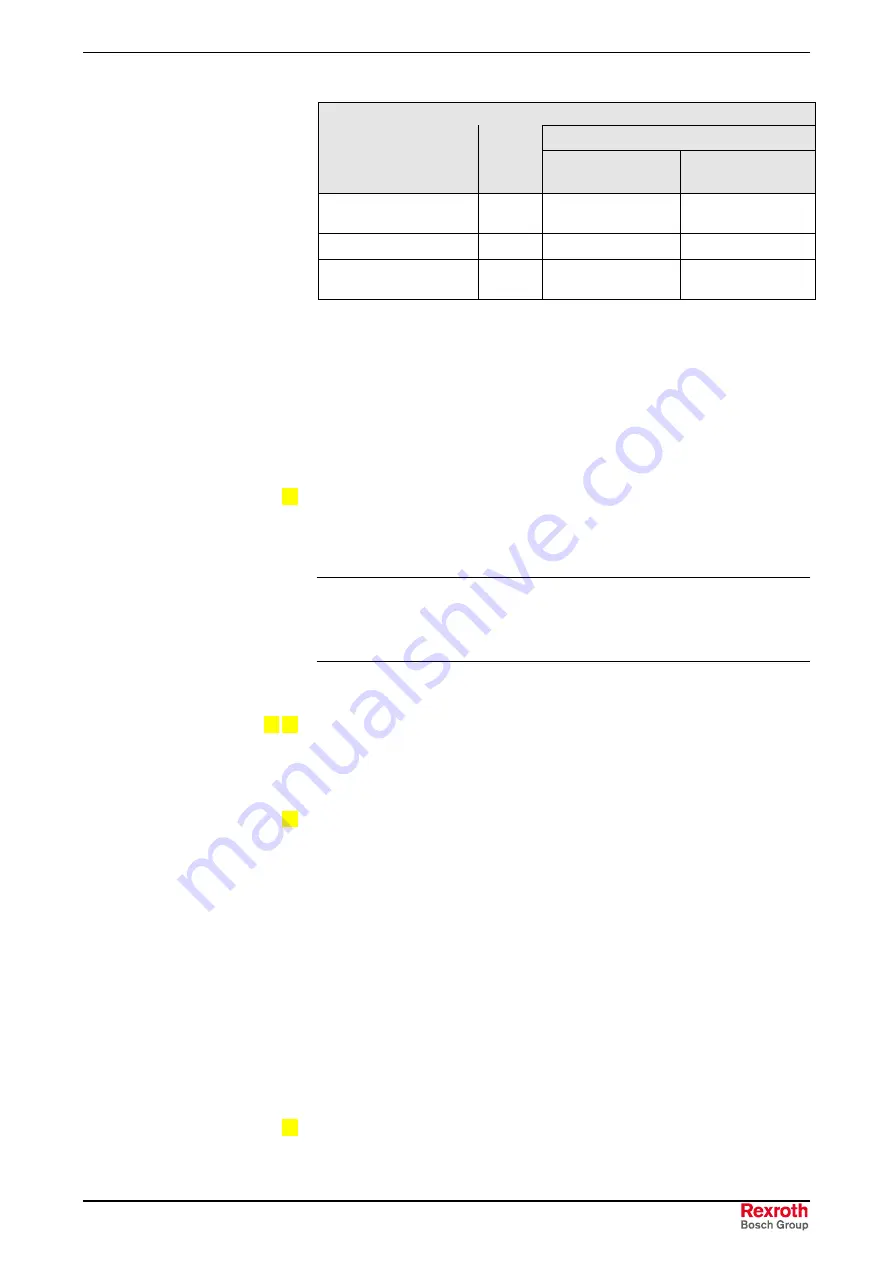
Output Shaft
with keyway
Plain
shaft
Balanced with
complete key
Balanced with half
key
Without shaft sealing
ring
H
Q
L
With shaft sealing ring
G
P
K
with labyrinth seal
(only for frame size 225)
F
R
---
Fig. 6-3:
Output shaft options
Motors with a keyway are always supplied with a key.
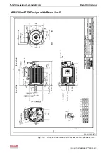
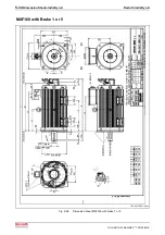
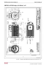
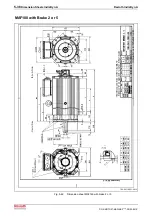
The motor drive shafts of frame sizes 130…225 have threaded centering
holes on the end face in "DS" version in accordance with DIN 332, sheet
2. For details, see the respective motor dimension sheet.
Please observe the supplementary notes on shaft sealing ring, drive
shaft, and labyrinth seal in chapter 9.12, "Drive Shaft".
9. Holding Brake
Up to frame size 180, IndraDyn A motors are optionally available with
integrated holding brake and different holding torques. Depending on the
application, an "electrically-clamped" or "electrically-released" holding
brake can be selected.
Note:
The motor holding brake is not suitable for the protection of
personnel or as a service brake! Heed the notes regarding
holding brakes in chapter 9 "Application Notes" and chapter 12
"Startup".
10. Design
IndraDyn A motors are available in the design 05 (flange mounting) or
design 35 (flange and foot installation). The permitted conditions of
installation are explained in chapter 9 "Notes Regarding Application".
11. Bearing
The standard bearing (option "N") consists of deep-groove ball bearings
in all IndraDyn A motors.
Reinforced bearings (option "V") can be used to taking up high radial
forces. With reinforced bearing, there is an additional cylindrical-roller
bearing at the drive side next to the deep-groove ball bearing.
The high-speed suspension (option “H“) consists of a deep-groove ball
bearing; it permits higher speeds at a reduced axial and radial load-
bearing capacity.
The bearing for the coupling connection (option "R") consists of a deep-
groove ball bearing. This bearing variant has a special bearing seat for
taking up rotating radial forces which may occur during motor operation
with coupling.
Heed the notes regarding bearings in chapter 4 ”Technical Data ….” and
chapter 9.17 "Bearing Variants".
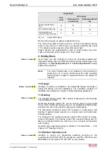
12. Vibration Severity Level
IndraDyn A motors are dynamically balanced according to the
requirements of DIN ISO 2373; the standard is step "R". With frame size
MAD/MAF100-180, options ”S” and ”S1” can be selected.
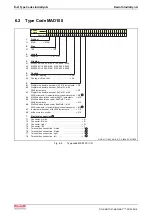
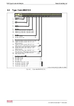
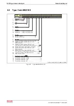
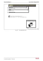
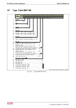
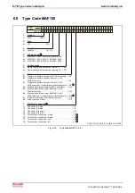
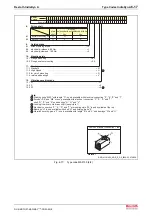
Abbrev. column 22
Abbrev. column 24 25
Abbrev. column 27
Abbrev. column 28
Summary of Contents for Rexroth IndraDyn A Series
Page 10: ...VIII Table of Contents Rexroth IndraDyn A DOK MOTOR MAD MAF PR03 EN P ...
Page 14: ...1 4 Introduction to the Product Rexroth IndraDyn A DOK MOTOR MAD MAF PR03 EN P ...
Page 150: ...5 42 Dimension Sheets IndraDyn A Rexroth IndraDyn A DOK MOTOR MAD MAF PR03 EN P ...
Page 174: ...6 24 Type Codes IndraDyn A Rexroth IndraDyn A DOK MOTOR MAD MAF PR03 EN P ...
Page 196: ...8 16 Connection Techniques Rexroth IndraDyn A DOK MOTOR MAD MAF PR03 EN P ...
Page 238: ...9 42 Application Notes Rexroth IndraDyn A DOK MOTOR MAD MAF PR03 EN P ...
Page 256: ...12 10 Operating IndraDyn A Motors Rexroth IndraDyn A DOK MOTOR MAD MAF PR03 EN P ...
Page 285: ...Rexroth IndraDyn A Index 14 5 DOK MOTOR MAD MAF PR03 EN P ...
Page 286: ...14 6 Index Rexroth IndraDyn A DOK MOTOR MAD MAF PR03 EN P ...
Page 287: ......


