Rexroth IndraDyn A
Application Notes
9-5
DOK-MOTOR*-MAD/MAF****-PR03-EN-P
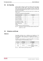
9.6
Frame Shape and Installation Position
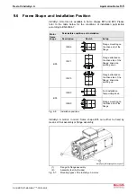
IndraDyn A motors are available in frame shapes B05 and B35. Please
refer to the table below for the conditions of installation permissible
according to EN 60034-7.
Permissible conditions of installation
Motor
frame
shape
Description
Sketch
Setup
IM B5
Flange mounting on
the drive end of the
flange
IM V1
Flange attached on
the drive side of the
flange; drive side
pointing down
B05
IM V3
Flange attached on
the drive side of the
flange; drive side
pointing up
IM B3
Foot installation
feet pointing down
B35
IM B5
Flange mounting on
the drive end of the
flange
Fig. 9-6:
Installation positions
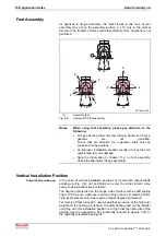
IndraDyn A motors in motor frame shape B35 can either be fixed by
means of foot assembly or flange assembly.
IndraDynA_Befestigungsbohrungen.tif
(1):
Flange for flange assembly
(2):
Assembly feet (both sides)
Fig. 9-7:
Mounting types of the IndraDyn A motors
Summary of Contents for Rexroth IndraDyn A Series
Page 10: ...VIII Table of Contents Rexroth IndraDyn A DOK MOTOR MAD MAF PR03 EN P ...
Page 14: ...1 4 Introduction to the Product Rexroth IndraDyn A DOK MOTOR MAD MAF PR03 EN P ...
Page 150: ...5 42 Dimension Sheets IndraDyn A Rexroth IndraDyn A DOK MOTOR MAD MAF PR03 EN P ...
Page 174: ...6 24 Type Codes IndraDyn A Rexroth IndraDyn A DOK MOTOR MAD MAF PR03 EN P ...
Page 196: ...8 16 Connection Techniques Rexroth IndraDyn A DOK MOTOR MAD MAF PR03 EN P ...
Page 238: ...9 42 Application Notes Rexroth IndraDyn A DOK MOTOR MAD MAF PR03 EN P ...
Page 256: ...12 10 Operating IndraDyn A Motors Rexroth IndraDyn A DOK MOTOR MAD MAF PR03 EN P ...
Page 285: ...Rexroth IndraDyn A Index 14 5 DOK MOTOR MAD MAF PR03 EN P ...
Page 286: ...14 6 Index Rexroth IndraDyn A DOK MOTOR MAD MAF PR03 EN P ...
Page 287: ......


