40/54 Installation
Bosch Rexroth AG
, MIT: LU 2, 3 842 358 814/2017-01
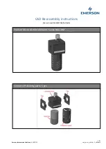
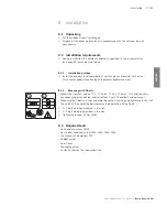
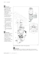
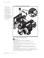
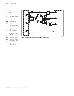
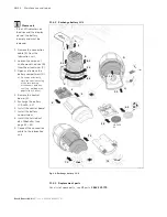
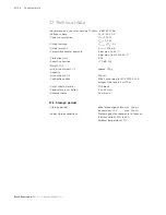
Fig. 21:
B02
B06
B05
B08
B07
B04
B01
B09
B10
B12
B03
B11
B13
Q3
Q2
Q1
1
out
1
out
1
out
&
and
&
and
&
and
Set
Reset
Q
latching relay
Set
Reset
Q
latching relay
1
120 sec
50 sec
or
on delay
50 sec
on delay
on delay
1
or
1
or
1
inv
2
in
1
in
3
l3
l1
l2
in
1
inv
A
B
1
)
2
)
3
)
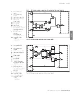
358 814-15
PLC programming suggestion with three output signals
A
:
PLC-terminal strip
Inputs
B
:
PLC-terminal strip
Outputs
l1
:
Cable white, output OK
l2
:
Cable black, output Err
l3
:
Cable brown,
voltage supply
B05
No signal green
B06
No signal red
B08
Cable break
1
):
Connect output B04
directly to the input B13,
if B11 B12 is not to be
used.
2
):
When using B13, l3:
Fault indication only when
the lubrication unit is
powered.
3
):
B11, B12 optional
Q1
:
Output Q1 = High if:
• normal function
Q2
:
Output Q1 = High if:
• Oil container empty
Q3
:
Output Q2 = High if:
• Fault
• Cable break
358814_2017_01_EN.indd 40
16.01.2017 13:38:19