5-12
Operating Instructions
IndraDynA_ATEX
DOK-MOTOR*-IDYN*A*ATEX-IB02-D5-P
Protective conductor
terminal on motor size
Nominal
cross-section
Terminal area
100...130
4 mm²
4 mm² (finely stranded)
6 mm² (single-wire)
160...180
10 mm²
10 mm² (finely stranded)
10 mm² (single-wire)
Fig. 5-9:
Terminal for grounding conductor
Cooling for MAD motors
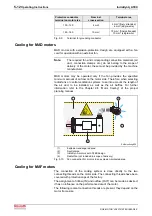
MAD motors with explosion-protection design are equipped with a fan
cowl for operation with an external fan.
Note:
The required fan and corresponding connection materials (air
duct, connection clamps, etc.) do not belong to the scope of
delivery of the motor; these must be provided by the machine
manufacturer.
MAD motors may be operated only if the fan provides the specified
minimum amount of air flow on the motor side. Therefore, when selecting
radial fans or central ventilation systems, take into account the length of
the air duct to be installed, as well as the air baffles. For further
information refer to the Chapter 9.8 “Motor Cooling” of the project
planning manual.
1
4
3
2
Ex-Belueftung.EPS
(1):
Explosion-endangered area
(2):
Neutral area
(3):
IndraDyn A motors with ATEX design
(4):
Radial fan (not included in scope of delivery)
Fig. 5-10:
Fan connection for motors in an explosion-protected area
Cooling for MAF motors
The connection of the cooling system is done directly to the two
connecting threads on the motor side. The connecting threads have been
covered with protective caps at the factory.
The assignment of inflow (IN) and outflow (OUT) can be made as desired;
it has no influence on the performance data of the motor.
The following coolant connection threads are present, they depend on the
motor frame size.


