IndraDynA_ATEX
Operating Instructions
5-9
DOK-MOTOR*-IDYN*A*ATEX-IB02-D5-P
Power Connection
Proceed as follows to connect the power cable in the terminal box of the
motor:
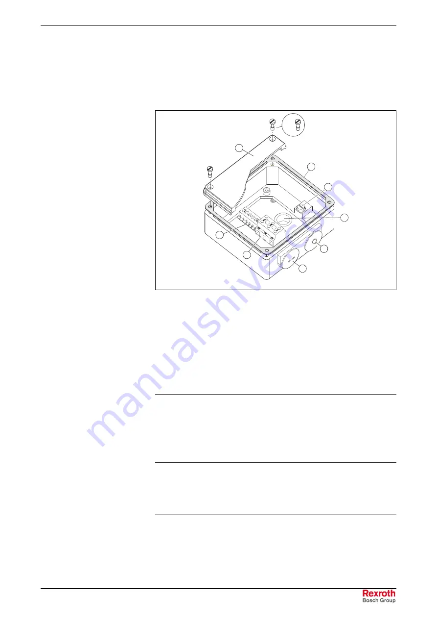
1. Unscrew and remove the 4 fastening bolts on the lid (1) of the
terminal box and open the lid.
1
2
4
6
5
3
4 x
7
8
MAx_Power_Box_ATEX.eps
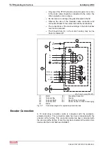
(1):
Lid
(2):
Gasket
(3):
PE connection
(4):
Cable entry
(5):
U-V-W power connection
(6):
Terminal strip
(7):
Purging connection port
(8):
Through hole
Fig. 5-6:
Terminal box
2. Remove the screw plug (4) of the metric screw on the side of the
terminal box and guide the power cable through this opening and into
the terminal box.
3. Attach the power cable to the terminal box. Use the cable gland
located on the power cable.
4. The wires are arranged according to Fig. 5-7.
Note:
Ensure that the wires are sufficiently clamped inside the wire
end ferrules. The connections of the ring terminals must be
tightened with:
•
Thread
M6
!
4 Nm
•
Thread
M8
!
9 Nm
•
Thread
M10
!
18 Nm
5. Fasten the lid (1) of the terminal box using all 4 fastening bolts
secured with Loctite 243. Before tightening the bolts, make sure that
the gasket (2) between the lid and the terminal box housing is
correctly positioned.
Notes:
•
The brake connections are assigned only if the motor was
manufactured with the "brake" option.


