39 / 74
MKE Synchronous Servomotors
Assemble transmission elements
Bosch Rexroth AG
R911402016, Edition 02
Table 15: Permissible shock load for MKE motors
Frame size
Maximum allowed shock load
(11
ms)
Axial
Radial
MKE037
10 m/s²
1000 m/s²
MKE047
10 m/s²
1000 m/s²
MKE098
10 m/s²
300 m/s²
MKE118
10 m/s²
200 m/s²
8
Assembly
8.1
Flange assembly
NOTICE
Motor damage due to ingress of liquids!
Liquid which exists over a longer period on the
shaft sealing ring of the output shaft can ingress
into the motor and cause damage.
−
Ensure that liquid cannot be present at the
output shaft.
−
Do not mount any open gearboxes (gear-
boxes that are not hermetically sealed).
Use all motor mounting holes to mount the motor
safely to the machine. For details on mounting
holes, please refer to the dimension sheets.
•
If coupling is direct, ensure that the support
is plane and the orientation is precise.
•
Avoid pinching or jamming the centering
collar on the motor side.
•
Avoid damaging the receptacle fit on the
plant side.
•
Use screws and washers for flange assembly
according to
.
8.2
Assemble transmission
elements
NOTICE
Motor damage due to strikes onto the motor
shaft
Do not strike the shaft end and do not exceed the
allowed axial and radial forces of the motor.
Fit and pull off the transmission elements such as
pulleys and couplings only with suitable equip-
ment; heat them, if necessary.
•
Avoid inadmissible belt tensions. Please con-
sider the allowed radial and axial forces in the
project planning manuals.
•
The balancing state of transmission elements
must comply with the full-key balancing of
the motors.
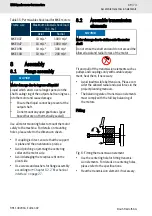
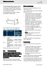
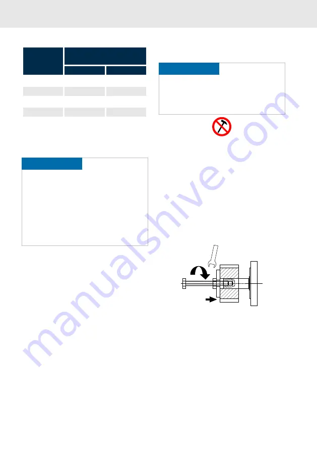
Fitting
Fig. 6: Fitting the transmission element
•
Use the centering hole for fitting transmis-
sion elements. For details on centering holes,
please refer to the specifications.
•
Heat the transmission element, if necessary.

