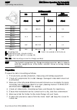
B05 (flange assembly)
Hole
Screw (8.8)
Wash-
er DIN EN 28738
Ø [mm]
Type
1)
M
GA
[Nm]
Ø [mm]
MSK050
9.0
M8×20
25
10
MSK060
MSK061
MSK070
11.0
M10×30
51
12
MSK071
MSK075
2)
MSK076
MSK100
14.0
M12×40
87
14
MSK101
MSK103
2)
MSK131
2)
18.0
M16×35
215
none
①
Mounting hole
M
GA
Tightening torque in Newton meters
1) Minimum screw length for screwing into
steel.
2) Motor not available in ATEX version.
Tab. 1-2: MSK mounting accessories (flange assembly)
The bolted connections for flange mounting must be able to absorb
both the weight force of the motor and the forces occurring during
operation.
Preparation
Prepare the motor mounting as follows:
1. Procure tools, auxiliary materials, measuring and testing equipment.
2. Check all components for visible damage. Damaged components must not
be mounted.
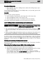
3. Make sure that all system dimensions and tolerances are suitable for motor
mounting (see dimension sheet in project planning manual “DOK-MOTOR*-
MSK*EXGIIK3-PR
⃞⃞
-
⃞⃞
-P” for details).
4. Check all components, mounting surfaces and threads for cleanliness.
5. Ensure that installation can be carried out in a dry, dust-free environment.
6. Make sure that the holder for the motor flange is free of burrs.
7. Remove the protective sleeve from the motor shaft and keep the sleeve for
future use.
10/27
Operating instructions
MSK Motors Operation For Potentially
Explosive Areas
Bosch Rexroth AG R911323850_Edition 05

