NOTICE
Damage due to improper mounting!
Mating motor and pump shaft carefully, aligning not to tilt the
wrench. Impacts onto motor or pump can cause damage and are
therefore not allowed.
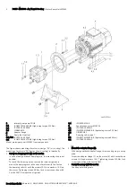
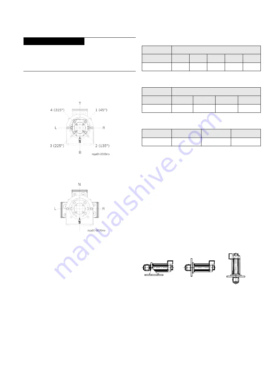
Screw the pump (1) with the motor by means of screws (1.1) and
washers (1.2) in the required orientation (T, 1 (45°), R, 2 (135°),
B, 3 (225°), L or 4 (315°) Tightening torque 210 Nm, lock screw
connection with Loctite 243®.
S
Suction connection (Option = B shown in the figure)
Pump mounting installation direction
Motor mounting orientation
4. Screw on pump foot
In the case of design without pump foot (3) this mounting step no
longer exists.
Fasten the pump foot (3) with the adapter flange (2) by means of
screws (3.2), washers (3.1, 3.3) and nuts (3.4) Tightening torque
210 Nm, lock screw connections with Loctite 243®.
Transport of motor-pump units by means of cranes or lifting
tools.
Transport with cranes or lifting gear is allowed only if suitable load-
securing devices, such as lifting straps, belts or chains are used.
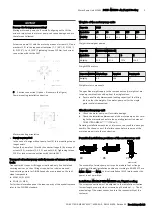
Load-securing points for DIN 580 eyebolts are provided on the indi-
vidual components.
▶ MSK133 (2× M12)
▶ PGH5 (1× M10)
For further information about the load capacity of the eyebolts please
refer to the DIN 580 standard.
Weights of the motor-pump units
Frame size
PGH5
Nominal size
63
80
100
125
160
Weight kg
39
40.5
42.5
45
49
Weight internal gear pumps
Frame size
MSK133-SA / MSK133-FN
Nominal size
B
C
D
E
Weight kg
91.6
111.0
127.0
146.0
Weight MSK motors
Frame size MSK133 Adapter flange
Pump foot
Damping rails
Weight kg
9.3
18.6
17
Weight motor components
The specified weights apply to the components only; weights of mo-
tor-pump combinations add up from the single values.
▶ Ensure a suffiently dimensioned loading capacity of the lifting
tools so that the weight of the motor-pump unit or the single
parts is safely transported.
Check motor-pump unit
▶ Check the motor-pump unit for visible damage.
▶ Check the installation dimensions of the motor-pump unit accord-
ing to the dimension sheets in the operating instruction manual
DOK-SYTROX-MPA01******-ITRS-xx-P.
Deviating installation measures or tolerances can result in a wrong as-
sembly. Check and correct the failure cause before you mount the
motor-pump unit into the construction.
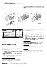
Permitted installation positions of the motor-pump unit
B3
B5
V1
mpa01-0008el
The assembly of motor-pump units can be made in foot or flange
mounting. Allowed installation positions according to EN 60037-7 are
IM B3, IM B5 and IM V1. Vertical installation IM V3 (motor under the
pump) is not permitted.
Installation MPA01-PGH5-MSK133 air / liquid cooling
The screw connection must be adjusted to the installation situation
(screw length, property class, screw-in depth, material, ...). The di-
mensioning of the screw connection is in the responsibility of the
customer.
Motor-Pump Unit MPA01 | PGH5 - MSK133 - Air / Liquid Cooling
3
DOK-SYTROX-MPA01*M13**-AS03-EN-P, R911341600, Edition 03 , Bosch Rexroth AG

