RE 95230-B/2021-12-01, Bosch Rexroth AG
Installation |
Analog amplifier RA 31
/48
7�4�4 Pin assignment
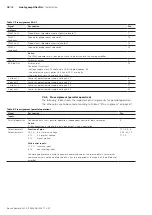
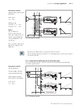
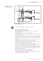
Table 7: Pin assignment RA2-1
Signal
Description
Pin
Inputs
PWR supply 1
Supply voltage for solenoid 1 and electronics
19
PWR supply 2
Supply voltage for solenoid 2 and electronics
20
Notice:
The supplies are permanently assigned to the PWM output stages. For example, if the supply
PWR supply 1 is interrupted, output stage 1 is no longer supplied.
The electronics works as soon as it is supplied with voltage via one of the two pins (19 or 20),
i.e. also if one of the two ports is torn off. This is useful, for example, for an emergency stop in a press.
GND supply 1
Ground (supply voltage solenoid 1)
6
GND supply 2
Ground (supply voltage solenoid 2)
8
Current range
switchover
Switches the current range over.
Defaults:
Not wired: 200 ... 600 mA
Connected with +U
Bat
:
400 ... 1200 mA
Notice:
If the circuitry of pin 18 fails (e.g. wire break), this halves the current.
18
Analog In 1
Differential voltage input (control solenoid 1):
non-inverting input
4
inverting input
17
Analog In 2
Differential voltage input (control solenoid 2):
non-inverting input
10
inverting input
22
Notice:
The differential voltage is a measure of the control; the higher the differential voltage,
the higher the current.
Ramp off
Switches the ramp function off.
Not wired:
Output signal is adjusted to input signal with time delay (time ramp).
Connected with +U
Bat
:
Output signal is adjusted to the input signal without time delay.
This is useful, for example, for individual external time ramps.
5
PWM frequency
Defines the PWM frequency of the proportional outputs.
Not wired: 100 Hz
Connected with +U
Bat
:
350 Hz
GND:
200 Hz
21
Parallel operation
Specifies the operating mode.
Not wired:
toggling operation,
interlocked control of solenoid 1 and 2
Connected with +U
Bat
:
parallel operation,
independent control of solenoid 1 and 2
9
Dig In
Switching input.
If a voltage between 5V ... U
Bat
is applied, the "Dig Out" switching output (pin 7) is activated.
Example:
The switching input can be used e.g. for an automatic emergency brake. For this purpose, the signal
is fed from the error output (pin 15) to pin 24 and a brake is controlled with the current of pin 7.
24
GND signal
Signal ground (potentiometer and sensor supply for differential input 1)
2
GND signal
Signal ground (potentiometer and sensor supply for differential input 2)
12


