34
/48
Analog amplifier RA
| Installation
Bosch Rexroth AG, RE 95230-B/2021-12-01
7�5 Examples of connection variants
Below, you can see some typical connection variants.
7�5�1 Variants for wiring an input or in parallel operation
If RA2-1 is used in parallel operation - pin 9 must be connected (U
Bat
) - both inputs
can be connected independently of each other.
The numbers in brackets indicate the pins of the second channel.
Pins 16/23, 3/11 and 2/12 are connected to each other in the device (bridged).
Of the cable monitoring is not used - pins 16 or 23 are not connected - the error LED
or the error output can be deactivated by connecting a resistance of approx. 5 kΩ.
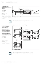
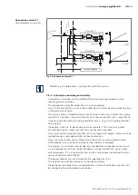
Wiring in connector
(23)
(10)
(22)
(11)
(12)
Channel 1
Setpoint
processing
Output stage
Solenoid 1
approx.
5.1 kΩ
8.4V
4.0V
Fig� 23: Connection variant 1
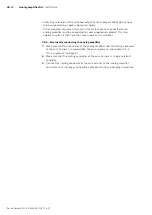
Monitoring of cable break is not possible with this variant.
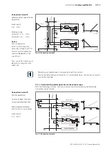
(23)
(10)
(22)
(11)
(12)
Wiring in connector
Channel 1
Setpoint
processing
Output stage
Solenoid 1
8.4V
4.0V
Fig� 24: Connection variant 2
Connection variant 1
Potentiometer between
4.0 V and GND connected.
Input signal
0 ... 4.0 V.
Connection variant 2
Potentiometer on
both sides at 8.4 V
Center connection at 4.0 V
Input signal
8.4 ... 4.0 ... 8.4 V

