background image

RE 95230-B/2021-12-01, Bosch Rexroth AG


Installation | 

Analog amplifier RA 37

/48

(2.4 k

(1 k

+
-

IM1

4.5V

0.5V

u

i

IM1

+

-

8.4V

4.0V

16

4

17

3

2

4.0V

12

11

22

10

+
-

8.4V

23

IM2

i

+

u

-

IM2

2.5V

2.5V

0.5V

4.5V

R1

R2

UST

Wiring  in connector

Channel 2

Setpoint

processing

Output stage

Solenoid 2

USETPOINT

USETPOINT

Channel 1

Setpoint

processing

Output stage

Solenoid 1

USETPOINT

Fig� 30:  Connection variant 8

Monitoring of cable break is not possible with this variant. 
Due to the reduced signal stroke of 2 V in both directions, the maximum current 
may not be reached.

7�5�3  Variants with parallel operation of the output stages

With the following variants, the two channels are simultaneously controlled by 
a common signal source.

9

UBatt

Parallel operation

Wiring  in connector

Channel 2

Setpoint

processing

Output stage

Solenoid 2

Channel 1

Setpoint

processing

Output stage

Solenoid 1

8.4V

4.0V

8.4V

4.0V

Fig� 31:  Connection variant 9

Connection variant 8

Setpoint value specification 
by joystick

Input signal
0.5 ... 4.5 V

Working range
Channel 1: 2.5 ... 4.5 V
Channel 2: 0.5 ... 2.5 V

Notice:

The stated values 
for R1 and R2 may vary 
since the voltage at pin 16 
(8.4 V) is within tolerance 
and also depends on the 
sum R1+R2.

The sum of R1 and R2 must 
be within a range of 2 kΩ 
and 5 kΩ

Connection variant 9

Parallel operation

Control of both channels 
using one potentiometer

Potentiometer between
8.4 V and 4.0 V connected.

Input signal
4.0 ... 8.4 V.

Summary of Contents for Rexroth RA 10 Series

Page 1: ...Instruction manual RE 95230 B 2021 12 01 replaces 08 2015 EN Analog amplifier RA ...

Page 2: ...ements concerning a certain condition or suitability for a certain application can be derived from our information The information given does not release the user from the obligation of own judgment and verification It must be remembered that our products are subject to a natural process of wear and aging The cover shows an example application The product delivered may differ from the image on the...

Page 3: ...14 5 3 Operating modes 15 5 4 Assignment and function of the LEDs and setting potentiometer 16 5 5 Identification of RA 17 6 Transport and storage 18 6 1 Transporting and storing the analog amplifier 18 7 Installation 19 7 1 Unpacking 19 7 2 Installation conditions 19 7 3 Installation position 20 7 4 Mounting the analog amplifier 20 7 4 1 Preparation 20 7 4 2 Mounting 20 7 4 3 Connector assembly 2...

Page 4: ...B 2021 12 01 10 Maintenance and repair 43 10 1 Cleaning and care 43 10 2 Inspection and maintenance 43 10 3 Repair 43 11 Removal and replacement 44 12 Disposal 44 13 Extension and conversion 44 14 Troubleshooting 45 15 Technical data 46 16 Alphabetical index 47 ...

Page 5: ...cumentation marked with the book symbol is available to you and you have understood and observed it Table 1 Required and supplementary documentation Title Document number Document type Analog amplifier RA series 10 Contains the permissible technical data connections main dimensions and circuit diagrams of standard versions 95230 Data sheet 1 3 Representation of information Uniform safety instructi...

Page 6: ...ing DANGER Identifies a dangerous situation that will result in death or serious injury if it is not avoided WARNING Identifies a dangerous situation that may result in death or serious injury if it is not avoided CAUTION Identifies a dangerous situation that may result in minor to moderate injury if it is not avoided NOTICE Property damage The product or surrounding area may be damaged 1 3 2 Symb...

Page 7: ...esignation product or amplifier will be used in the following 1 3 4 Abbreviations This documentation uses the following abbreviations Table 5 Abbreviations Abbreviation Meaning ANSI American National Standards Institute is an organization that coordinates the development of voluntary standards in the United States DIN Deutsches Institut für Normung German Institute for Standardization EMC Electrom...

Page 8: ...e current temperature vibration shock and other described environmental influences Its use outside of these specified and approved boundary conditions may result in danger to life and or cause damage to components which could result in sequential damage to the mobile working machine Serious personal injury and or damage to property may occur in case of non compliance with the appropriate regulatio...

Page 9: ...ponents Only trained and experienced specialists who are adequately familiar with both the components used and the complete system should implement system developments or install and commission electronic systems for controlling hydraulic drives Bosch Rexroth offers you measures supporting training in specific areas You can find an overview of the training contents on the Internet at www boschrexr...

Page 10: ...ch as unintended actuation or switching off of one or several solenoids cannot be reliably prevented In emergency situations or if important functions fail the operating voltage is to be externally interrupted To this end interruption of the electronics power supply has to be provided by means of an emergency stop switch The emergency stop switch must be installed in an easily accessible position ...

Page 11: ...en working on unsecured machines Property damage Switch off the relevant machine part and secure it against reactivation according to the parameters of the machine manufacturer CAUTION Improper cable and line routing Risk of stumbling and property damage Improper routing of cables and lines can cause a risk of stumbling as well as damage to equipment and components e g due to lines and connectors ...

Page 12: ...ironmental pollution Dispose of the product and packaging in accordance with the national regulations in your country Electrical voltage Property damage due to electrical voltage Always disconnect the voltage supply to the relevant machine system part before installing the product and or connecting or disconnecting the connector Protect the machine system against reactivation The warranty exclusiv...

Page 13: ...RE 95230 B 2021 12 01 Bosch Rexroth AG Scope of delivery Analog amplifier RA 13 48 4 Scope of delivery The scope of delivery exclusively includes the analog amplifier RA Fig 1 Analog amplifier RA ...

Page 14: ...or to actuate two devices independently of each other for example two individual axial piston units or valves The use of only one proportional output is possible An additional 1 A output is available for a switching function 5 2 Features The electronic analog amplifier offers the following features Optional interdependent locking of the proportional solenoid control Voltage supply for external com...

Page 15: ...h independent control Setting range ISolenoid Imin Imax 0 06 x Imax 0 8 x Imax 4 0 V Ucommand 8 4 V Fig 3 Parallel operation Imin and Imax control the minimum and maximum current that is applied to the respective outputs proportional solenoids Imin basically corresponds to an offset start current from which the solenoid responds Imax to the gain gradient As Imax and Imin are added an output curren...

Page 16: ... 6 Potentiometer minimum current Imin2 PWM current channel 2 7 Potentiometer downwards ramp tdown2 PWM current channel 2 8 Potentiometer upwards ramp tup2 PWM current channel 2 9 PWM current channel 2 I2 yellow LED 10 Power operating display green LED 11 Error error display red LED 12 PWM current channel 1 I1 yellow LED The brightness of LEDs I1 and I2 depends on the strength of the output current...

Page 17: ...021 12 01 Bosch Rexroth AG About this product Analog amplifier RA 17 48 5 5 Identification of RA The product is to be identified by means of the material number 1 on the analog amplifier 1 Fig 5 Material number RA ...

Page 18: ... is dropped continued use is not permissible because unseen damage may affect its reliability 6 1 Transporting and storing the analog amplifier Shock resistance Transport shock IEC 60068 2 27 3x in each direction positive negative and 15 g 11 ms in each axis Store analog amplifiers at an average relative humidity of 60 and at a temperature between 10 C and 30 C After a storage time of more than 5 ...

Page 19: ...g from the analog amplifier Check the analog amplifier for transport damage and completeness see chapter 4 Scope of delivery on page 13 Dispose of the packaging in accordance with the regulations in your country 7 2 Installation conditions Do not install the control unit near parts which generate considerable heat e g exhaust Radio equipment and mobile telephones must not be used in the driver s c...

Page 20: ...ss accordingly Fig 6 Installation position analog amplifier 7 4 Mounting the analog amplifier 7 4 1 Preparation 1 Use the material number on the sticker of the packaging unit or directly on the analog amplifier to check whether the correct analog amplifier is available see chapter 4 Scope of delivery on page 13 2 Compare the material number with the details in the order confirmation If the materia...

Page 21: ...d Junior Power Timer contacts type A For crimping Crimping hand device TE Connectivity part number 539635 1 Insert matrix TE Connectivity part number 539674 2 for Junior Power Timer contact 927775 3 or 927783 3 For disassembly Extraction tool TE Connectivity part number 968107 1 for Junior Power Timer contact 927775 3 or 927783 3 The mating connector R902603063 is available as a complete set One s...

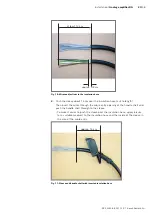
Page 22: ...and suitable tools must be purchased from the trade Individual wires and or several lines are to be introduced into the sleeve of the connector by bundling them in a PVC insulation hose of 15 to 18 mm in order to achieve type of protection IP65 Fig 8 correct Fig 9 incorrect It is recommended to start assembling the lines from the connector 1 Pull the wires and or lines into the insulation hose Let...

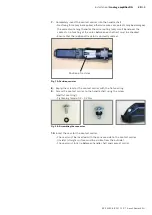
Page 23: ...lation hose cut to length Then insert the wires through the cable entry opening of the handle shell and push the handle shell through to the sleeve To make it easier to push the sleeve over the insulation hose apply talcum or a suitable medium to the insulation hose and the inside of the sleeve in the area of the cable entry approx 15 cm Fig 11 Sleeve and handle shell with inserted insulation hose...

Page 24: ... longer contacts 2 and 15 55 mm contact 3 and 16 60 mm etc The last wires of contacts 13 and 25 should not be longer than 12 cm 50 mm Casting for screw Contact 1 or 14 Fig 12 Cutting wires to length The contact carrier is positioned correctly if contacts 1 and 14 are on the side of the cable entry opening of the handle shell We recommend starting the cutting to length crimping and plugging from th...

Page 25: ...4 18050 Wire protruding max 1 mm Insulation crimped Insulation not crimped Correct crimping Incorrect crimping Hook Fig 14 Correct stripping length The catch of the contact must be engaged in the detent locking of the contact carrier Verify this by pulling on the line tensile test Immediately consider internal bridges and if necessary wiring elements resistance in the connector and install them ac...

Page 26: ...ges from UBat or 0V to switching inputs the incoming wires must always be connected to the contacts of the supplies first The bridges then lead to the switching inputs Bridges that are to be connected to an incoming wire of 0 5 mm2 gray must have a cross section of 0 25 0 35 mm2 since otherwise the supplied crimping contact will no longer crimp the insulation correctly Establish middle contacts by...

Page 27: ... they reach over the resistance or to the wire bending and extend about 5 mm over the insulation of the straight wire The external shrinkable tubing must protrude the component and the individual shrinkable hoses by approx 5 mm so that the connection wire of the resistance is insulated and safe mechanical protection of the connections is guaranteed The diameter must be selected so that in the shru...

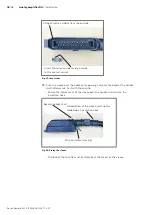
Page 28: ...pening The insulation hose end must reach into the handle shell by approx 1 to 1 5 cm via the terminal area of the cable clamp The contact carrier must still hang out on the opposite side of the cable entry opening no tension on the wires approx 1 1 5 cm Contact carrier hanging out Clamping collar Latches Fig 18 Bringing contact carrier into position 6 Screw on the clamping collar with the corresp...

Page 29: ...hecked Ensure that the optional resistor is correctly seated Position of resistor Fig 19 Position resistor 8 Equip the screw for the contact carrier with the flat seal ring 9 Screw the contact carrier to the handle shell using the screw and flat seal ring Tightening torque 0 4 0 7 Nm Fig 20 Assembling the connector 10 Insert the seal for the contact carrier The seal must be inserted with the conca...

Page 30: ...the sleeve over the cable entry opening and over the bead at the handle shell Afterwards fix it with the wire tie Ensure the correct seat of the sleeve over the handle shell and on the insulation hose Bead at handle shell Introduction of the sleeve must not be folded up at insulation hose Wire tie lateral closing Fig 22 Fixing the sleeve The lock of the wire tie must lie laterally at the recess of...

Page 31: ...tage input control solenoid 2 non inverting input 10 inverting input 22 Notice The differential voltage is a measure of the control the higher the differential voltage the higher the current Ramp off Switches the ramp function off Not wired Output signal is adjusted to input signal with time delay time ramp Connected with UBat Output signal is adjusted to the input signal without time delay This i...

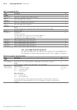
Page 32: ...y voltage 8 4 V 16 V mid ext 2 Sensor or potentiometer supply voltage 4 0 V 11 V pos ext 2 Sensor or potentiometer supply voltage 8 4 V 23 7 4 5 Pin assignment parallel operation The following table shows the important pin assignments for parallel operation The other pins are to be wired according to Table 7 Pin assignment on page 31 Table 8 Pin assignment parallel operation Signal Description Pin...

Page 33: ...control of solenoid 1 and 2 9 Potentiometer The potentiometer controls both differential inputs Function of pins 16 23 8 4 V internal voltage 3 11 4 V internal voltage 2 12 Signal ground Differential inputs 17 22 inverting input 4 10 non inverting input The voltage difference is used to generate command values In order to obtain a maximum command value a voltage difference of 4 V must in each case...

Page 34: ...Of the cable monitoring is not used pins 16 or 23 are not connected the error LED or the error output can be deactivated by connecting a resistance of approx 5 kΩ Wiring in connector 23 10 22 11 12 Channel 1 Setpoint processing Output stage Solenoid 1 approx 5 1 kΩ 8 4V 4 0V Fig 23 Connection variant 1 Monitoring of cable break is not possible with this variant 23 10 22 11 12 Wiring in connector C...

Page 35: ...4V 4 0V 8 0V 4 0V Fig 26 Connection variant 4 Monitoring of cable break is not possible with this variant 23 10 22 11 12 Wiring in connector Channel 1 Setpoint processing Output stage Solenoid 1 ISETPOINT ISETPOINT approx 5 1 kΩ 8 4V 4 0V Fig 27 Connection variant 5 Monitoring of cable break is not possible with this variant Connection variant 3 Setpoint value specification by control Input signal...

Page 36: ... Channel 2 Setpoint processing Output stage Solenoid 2 Channel 1 Setpoint processing Output stage Solenoid 1 8 4V 4 0V 8 4V 4 0V 8 4V 4 0V 4 0V Fig 29 Connection variant 7 Monitoring of cable break is not possible with this variant Connection variant 6 Setpoint value specification by control Input signal 0 10 V Working range 0 10 V R Resistances with identical values between 5 6 kΩ and 6 2 kΩ Conn...

Page 37: ...ges With the following variants the two channels are simultaneously controlled by a common signal source 9 UBatt Parallel operation Wiring in connector Channel 2 Setpoint processing Output stage Solenoid 2 Channel 1 Setpoint processing Output stage Solenoid 1 8 4V 4 0V 8 4V 4 0V Fig 31 Connection variant 9 Connection variant 8 Setpoint value specification by joystick Input signal 0 5 4 5 V Working...

Page 38: ...el 2 Setpoint processing Output stage Solenoid 2 Channel 1 Setpoint processing Output stage Solenoid 1 open 8 4V 4 0V 8 4V 4 0V Fig 32 Connection variant 10 For this connection type cable break monitoring is implemented by the internal current measurement at pin 16 In case of an error the error output is set The PWM outputs are not always switched off Connection variant 10 Potentiometer via switch...

Page 39: ...t an in phase excitation with the analog amplifier occurs e g at the analog amplifier fixing point If possible lines are to be routed inside the vehicle If the lines are routed outside the vehicle make sure that they are securely mounted Lines must not be kinked or twisted must not rub against edges and must not be routed through sharp edged ducts without protection Lines are to be routed with suf...

Page 40: ...his also applies to relays if they have the same supply as the amplifier 7 5 5 Electrically connecting the analog amplifier 1 Make sure that the connector of the analog amplifier and the mating connector of the wire harness are compatible For pin assignment see chapter 7 4 4 Pin assignment on page 31 2 Make sure that the mating connector of the wire harness is in de energized condition 3 Connect t...

Page 41: ... the vehicle The analog amplifier must be set before commissioning so that at 100 of the command value signal it supplies the desired command value current at its output To set the analog amplifier proceed as follows 1 Turn the setting potentiometer at the RA for Imin and Imax completely to the left 2 Set the setpoint potentiometer or the joystick the sensor or the corresponding signal source in t...

Page 42: ...t potentiometer tdown The ramp setting process may have to be repeated several times With ramp operation the initial reaction may be too strong In this case it can be reduced by turning the setting potentiometer Imin to the left Afterwards the maximum modulation has to be readjusted again by setting the setpoint potentiometer to 100 and setting the desired maximum modulation by turning the setting...

Page 43: ...ith high pressure and or steam jet equipment For cleaning and care of the analog amplifier observe the following Check whether all the seals and fittings on the plug in connections are securely seated to ensure that no moisture can penetrate into the analog amplifier and the installation space during cleaning Use only water and if necessary a mild cleaning agent to clean the analog amplifier Never...

Page 44: ...disposal of the analog amplifier can lead to environmental pollution Dispose of the analog amplifier and the packaging material in accordance with the national regulations in your country 13 Extension and conversion You must not convert the analog amplifier The Bosch Rexroth warranty only applies to the configuration as delivered The warranty will be voided if the unit is modified or extended ...

Page 45: ...y General functional impairments Make sure that all ground wires are connected as intended Malfunctions in parallel operation Make sure that the parallel operation input pin 9 is connected Machine provides too little power Check the current range switching pin 18 Check the settings for Imin and Imax Proportional solenoids do not react Make sure that the differential amplifier is correctly connecte...

Page 46: ...The permissible technical data of the analog amplifier can be found in the online product catalog in the data sheet Type Data sheet Link online product catalog QR code RA 95230 www boschrexroth com p RA2 1 For further information on the display please refer to www boschrexroth com mobile electronics ...

Page 47: ...tification 17 Inspection 43 Installation 19 Preparation 20 Installation conditions 19 Intended use 8 M Maintenance 43 O Operation 43 P Product description 14 Property damage 12 Q Qualification 9 R Removal 44 Repair 43 Replacement 44 Required documentation 5 S Safety instructions 8 General 9 Product specific 11 Signal word 6 Scope of delivery 13 Storage 18 Symbols 6 T Technical data 46 Transport 18...

Page 48: ...traße 2 71701 Schwieberdingen Germany Service phone 49 0 9352 40 50 60 info bodas boschrexroth de www boschrexroth com Subject to change RE 95230 B 2021 12 01 Your local contact person can be found at https addresses boschrexroth com ...

Reviews: