RE 95230-B/2021-12-01, Bosch Rexroth AG
Installation |
Analog amplifier RA 39
/48
9
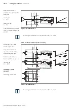
UBatt
Parallel operation
Wiring in connector
Channel 2
Setpoint
processing
Output stage
Solenoid 2
Channel 1
Setpoint
processing
Output stage
Solenoid 1
USETPOINT
USETPOINT
USETPOINT
approx.
5.1 kΩ
8.4V
4.0V
8.4V
4.0V
10.0V
10.0V
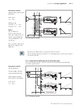
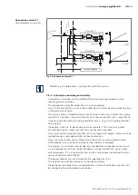
Fig� 33: Connection variant 11
Monitoring of cable break is not possible with this variant.
7�5�4 Information on wiring and circuitry
• Connections to systems with a different electrical ground or power source
require galvanic isolation.
• The product may only be wired when it is de-energized.
• Lines to the electronics must not be routed close to other power-conducting lines
in the device or vehicle.
• The wiring harness should be mechanically fixed in the area in which the analog
amplifier is installed. The wiring harness must be mounted in such a way that an
in-phase excitation with the analog amplifier occurs (e.g. at the analog amplifier
fixing point).
• If possible, lines are to be routed inside the vehicle. If the lines are routed
outside the vehicle, make sure that they are securely mounted.
• Lines must not be kinked or twisted, must not rub against edges and must not be
routed through sharp-edged ducts without protection.
• Lines are to be routed with sufficient distance to hot or moving vehicle parts.
• PWM outputs must not be connected to one another or bridged.
• The outputs must not be used to operate incandescent lamps due to the inrush
current properties of these loads. Exceptions are permissible for signal lamps
with low power if it is ensured that the inrush current does not exceed the limit
values of the data sheet 95230.
• The power outputs are not suitable for the operation of LEDs.
• The outputs may not be externally connected to battery.
• Proportional solenoids which are operated in a current-controlled way must not
be connected to spark-suppression diodes.
Connection variant 11
Potentiometer via switch


