44/96
Pressure and flow control system SYDFE1 series 2X, 3X
| Mounting
Bosch Rexroth AG, Edition 10.2021, RE 30011-B
SYD_015
+
-
=
b
a
c
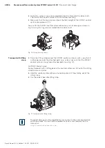
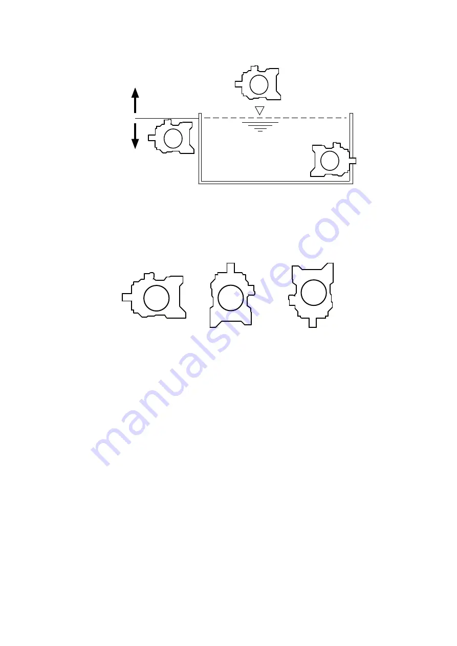
Fig. 18: Installation position
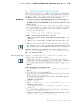
The following installation orientations are possible:
• Pos.1 horizontal: Shaft end horizontal
• Pos.2 vertical: Shaft end upwards
• Pos.3 vertical: Shaft end downwards (possible only with pump variant 0975)
SYD_016
3
2
1
Fig. 19: Installation orientations
7.3.2 Piping
The installation positions and installation orientations shown in Figs. Fig. 18 and
Fig. 19 determine the installation of
• suction lines
• case drain lines
• bleed lines
Make sure for all installation positions that always the higher of drain ports “L”
or “L1” is piped. Moreover, the distance between the end of installed pipes and
the minimum oil level must not be shorter than the specified minimum distance
(immersion depth “E”)
When installing suction and case drain lines, take care that the routing is straight
and short and has as few bends as possible.
When the system is at rest, the lines drain automatically in the course of time due
to the own weight of the hydraulic fluid.
Moreover, the different specific densities of hydraulic fluids must be taken into
account, since fluids with a higher density are more difficult to aspire and also
flow down more quickly. The limit speeds for hydraulic fluids with high density
(≥ mineral oil 0.87 g/ml) are specified in data sheet RE 90223.
Installation orientation
To be noticed

