46/96
Pressure and flow control system SYDFE1 series 2X, 3X
| Mounting
Bosch Rexroth AG, Edition 10.2021, RE 30011-B
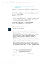
chamber, the drain line should be returned to the tank as far away as possible
from the suction port.
▶ External influences of pressure, e.g. from manifold tank lines, on the pump
drain port or the pump case are not permitted.
7.4
INSTALLING THE SYDFE1 CONTROL SYSTEM
CAUTION
Uncontrolled movements of the control system!
Risk of injury.
▶ Make sure that the SYDFE1 control system is safely mounted!
NOTICE
Damage caused by missing seals and plugs!
Liquids and foreign particles may penetrate and damage the product.
▶ Before starting the installation make sure that all seals and plugs of
connections are tight.
7.4.1 Preparations
1.
Check the scope of delivery for completeness and damage in transit.
2.
Compare the material number and designation (ordering code) with the details
on the order confirmation.
If the material number for the SYDFE1 control system is not identical with that
on the order confirmation, contact Rexroth Service for clarification, see chapter
10.5 “Spare parts” on page 75 for address.
3.
Before installing the SYDFE1 control system, completely empty it to prevent
mixing with the hydraulic fluid used in the system.
4.
Check the direction of rotation of the SYDFE1 control system (shown on the
nameplate) and make sure that this corresponds to the actual direction of
rotation of the motor.
The direction of rotation as specified on the nameplate shows the direction of
rotation of the SYDFE1 control system as viewed on the drive shaft. For
information on the direction of rotation of the motor, please refer to the motor
manufacturer’s operating instructions.
7.4.2 Dimensions of connections
The data sheet contains the dimensions for all connections to the SYDFE1 control
system. Also observe the instructions provided by the manufacturers of the other
components when selecting the required tools.

