54/96
Pressure and flow control system SYDFE1 series 2X, 3X
| Mounting
Bosch Rexroth AG, Edition 10.2021, RE 30011-B
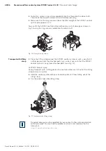
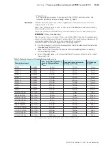
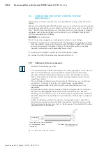
Favorable places of installation of pressure transducers turned out to be not in the
direct vicinity of the pump, but, for example, downstream of the (flexible) pressure
hose:
• Always between pump and check valve (if fitted)
• Do not use minimess lines
We recommend suspended mounting of the pressure transducer so that bleeding
problems (and hence control oscillations) can be ruled out right from the start.
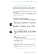
If, due to the installation orientation of the pump, a pressure transducer must
be installed “vertically” directly in the pump or in the pre-load valve, we
recommend another place of installation for the pressure transducer.
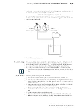
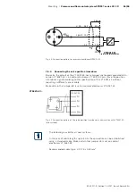
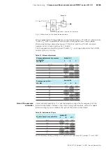
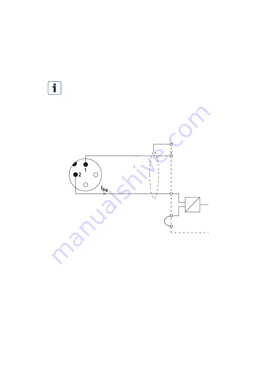
Pressure transducers of type HM20...C... are provided with a 2-wire current
interface and can be connected to control electronics VT 5041-3X as shown below.
The voltage supply for the pressure transducer must be provided in accordance
with the data sheet.
For more detailed information about the pressure transducer HM20...C..., see data
sheet RE 20272.
Recommended cable type: LiYCY 2 x 0.25 mm²
Fig. 23: Connection pattern for pressure transducer
HM20...C...
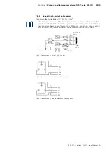
Pressure transducers of type HM20...H... are provided with a voltage output of
0.1...+10 V as actual pressure value signal and can be connected to control
electronics VT 5041-3X as shown on the figure below.
The voltage supply for the pressure transducer must be provided in accordance
with the data sheet.
For more detailed information about the pressure transducer HM20...H..., see data
sheet RE 30272.
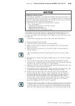
Place of installation of
the pressure transducer
Mounting orientation of
the pressure transducer
Pressure transducer
HM20...C...
32a
26a
U
B
18 .... 36 V
Signal 4 .... 20 mA
8c
10c
I
U
28a
VT5041-3X/..
Pressure transducer
HM20...H...

