RE 30011-B, Edition 10.2021, Bosch Rexroth AG
Commissioning |
Pressure and flow control system SYDFE1 series 2X, 3X
65/96
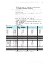
Attention: If 0 V is externally connected to 10c by means of a jumper, J16 must
not be set.
8.1.5 Switching on the supply voltage for the control electronics
▶ Before switching the supply voltage on, thoroughly re-check all cable
connections (including any intermediate terminals, if provided).
Measurements at the front-sided test jacks or at the rear male or female
multi-point connector may only be taken with instruments having an internal
resistance of Ri > 100 kOhm.
The controller card may only be plugged or withdrawn when disconnected from
the power supply.
The switch-on sequence of electronics/hydraulics is described in chapter 5.12.1
“Activation sequence of electronics/hydraulics“ on page 37.
For this, the drive motor of the pump must be switched off. For initial
commissioning, the following proceeding is recommended:
▶ Switch on voltage supply
The green LED “Ub“ signals that the voltage supply is active
▶ Activate enable
The green LED “En.“ signals that the enable is applied
The red LED “Err.“ (fault) must not be ON
If this state is not reached, a fault must have occurred.
Possible faults:
The green LED “Ub“ is OFF
▶ Check the supply voltage
▶ Check fuse F1
The red LED “Err.“ (fault) is ON
▶ The enable contact must be made, i.e. “En.“ is ON
▶ Measure the actual pressure value at test jack 2 (must be ca. 0 V)
In the case of a negative voltage of less than ca. -1 V or voltages greater than ca.
+12 V a fault message is output.
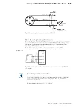
▶ Check the signal path to the pressure transducer.
The signal range of the pressure transducer must correspond to the
configuration of switch S2! (Current, voltage, zero point).
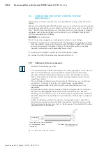
• The swivel angle indicator shows ca. 100 %, and a voltage of ca. 8...10.5 V must
be measurable at test jack 4. (The pump, which is at rest, is mechanically fully
swiveled out by the spring in the counter-piston).
• If the swivel angle indicator shows “minus 100“ or ca. -10 V is measured at test
jack 4, inspect the cabling of the swivel angle transducer.
• When monitoring of the control error was activated (J9 ON), check the valve
command value at socket 5. Should the valve command value exceed an amount
of 4 V, the command values must be adjusted or J9 set to “OFF” for trial and
testing.
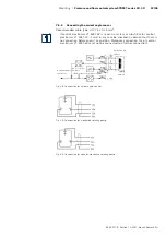
• If none of the points above applies, check the connection of the valve position
transducer and the solenoid.

