RE 30011-B, Edition 10.2021, Bosch Rexroth AG
Commissioning |
Pressure and flow control system SYDFE1 series 2X, 3X
71/96
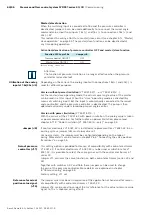
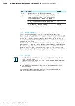
▶ By applying a voltage within the range of 0…+10 V to terminals 18c(+) and 20c(-
) a power limit of between 0 % and 100 % can be set. The selected value can
be checked at test jack 8 (front panel).
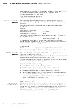
Calculation of the rated pump power
Motor power
P
M
= 15 kW
Speed n = 1500 min
-1
Displacement V
G
= 100 cm³ (pump size)
Maximum pressure
p
max.
= 315 bar
Efficiency η
mh
= 1 (theoretical value)
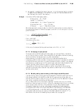
Maximum pressure = pressure [bar], at which the actual pressure value output of
the control electronics VT 5041-3X outputs a value of +10 V at test jack 2 (= actual
pressure value).
P
100%
=
V
G
[cm
3
] · n [min
-1
] · p
max
[bar]
600,000 · η
mh
[kW]
P
100%
= 78.75 kW
Calculation of the ratio
(p · α)
max
=
P
M
P
100%
· 100 % = 19 %
In this case, the power limit would have to be set to 19 %, i.e. 1.9 V.
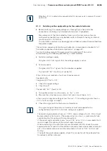
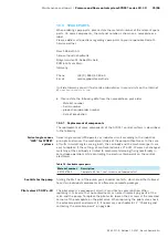
8.1.13 Performing a functional test
Once you have tested the hydraulic fluid supply, you must perform a functional
test on the machine or system. The functional test should be carried out according
to the instructions of the machine or system manufacturer.
Before delivery, the SYDFE1 control system is checked for operability in
accordance with the technical data. During commissioning, it must be ensured that
the SYDFE1 control system was installed into the machine or system in accordance
with the plans and drawings. Use the swivel angle indicator to check whether the
SYDFE1 control system correctly swivels in and out during operation.
The position of the swivel angle indicator and the assignment of the swiveling
direction to the direction of rotation and control can be found in the associated
technical data sheets.
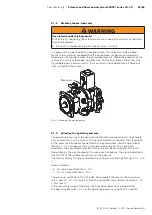
8.1.14 Bleeding during commissioning or after longer standstill periods
Just like during commissioning you have to bleed the SYDFE1 control system also
after longer periods of standstill in order that the pump can build up pressure
directly after the electric motor starts up. The necessity for this depends, however,
also on the installation orientation of the pump.
You can bleed the system manually by “opening” the pressure line at a suitable
point (e.g. minimess port, valve, etc.). When an unloading valve to tank is installed
(quasi “pressureless start-up”), this procedure can also be automated when
the electric motor starts up: The valve merely needs to be activated briefly; a
continuous pressureless start-up as described in the following is not required.
If a SYDZ pre-load valve is installed and the pump does not build up pressure
or displace hydraulic fluid, this valve must be bled additionally at point “P” as
described in section 8.1.8 “Bleeding the pre-load valve“ on page 67.
Example

