RE 30011-B, Edition 10.2021, Bosch Rexroth AG
Troubleshooting |
Pressure and flow control system SYDFE1 series 2X, 3X
83/96
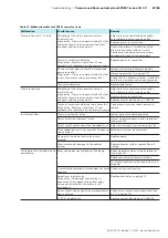
▶ Remove control electronics VT 5041-3X from the rack
– Female multi-point connector 14a to 10a:
ca. 36 Ohm
– Female multi-point connector 12a to 10a:
ca. 36 Ohm
– Female multi-point connector 12a to 14a:
ca. 50 Ohm
Note:
This measurement will not provide any information on the correct wiring
of counter-clockwise and clockwise rotating pumps (see also chapter
7.6.5 “Connecting the swivel angle sensor“ on page 57).
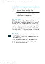
• Primary and secondary side of the position transducer
– The signals to the position transducer (primary side) as well as from the
position transducer (secondary side) are checked for plausibility. Should one
of the two LEDs be lighted, check whether the position transducer is wired
correctly.
VT 5041-3X
Valve position
transducer
Primary side
Connection 8a/22a
Connection 1 and 2
Secondary side
Connection 4a/6a
Connection 3 and 4
• Signal level of position transducer position < -11 V
– When the valve is not activated (e.g. no enable given for the valve or the
solenoid connector is unplugged), the actual valve value will leave the
permitted operating range. This will result in an individual fault.
Moreover, the resistance of the cables can be measured with connectors plugged
in on the valves.
▶ Switch voltage off
▶ Remove control electronics VT 5041-3X from the rack
– Female multi-point connector 28c to 30c:
ca. 2-4 Ohm (solenoid)
– Female multi-point connector 4a to 6a:
ca. 103 Ohm (position
transducer)
– Female multi-point connector 8a to 6a:
ca. 115 Ohm (position
transducer)
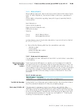
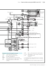
This monitoring function is active only when jumper J9 is set (= ON).
The monitoring feature, which was newly added compared with control electronics
VT 5041-2X, continuously checks the valve command value (= control difference x
controller gain) and signals an error, as soon as the amount exceeds the value of 4
V, which can be measured at test jack 5, for more than one second.
To remain compatible with series 2X control electronics in terms of function, this
monitoring feature is deactivated with the factory setting (jumper J9 open).
By setting jumper J9 you can add this fault signal to the collective fault signal.
It must be noted that when this fault signal is deactivated, the LED “v-soll“ on
the printed-circuit board continues to signal a control error as fault, but will not
evaluate it.
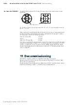
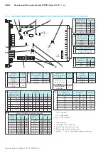
The voltages of +15 V and -15 V generated by the own power supply unit of the
VT 5041-3X are monitored for the following levels.
• Monitoring of internal v15 V for values less than 10 V
(fault is signaled by LED, see Fig. 36, item 9: US +15 V)
• Excessive difference b15 V and -15 V (= unbalance)
Monitoring of actual
valve value sensing
Monitoring of the control
deviation
Monitoring of internal
voltage supply

