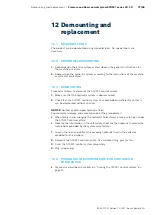
RE 30011-B, Edition 10.2021, Bosch Rexroth AG
Annex |
Pressure and flow control system SYDFE1 series 2X, 3X
91/96
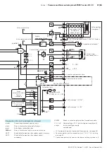
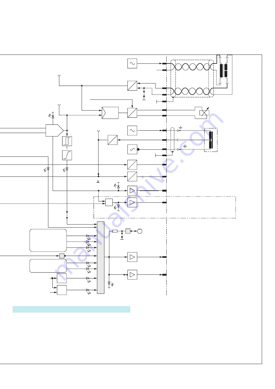
17.2 BLOCK CIRCUIT DIAGRAM OF CONTROL ELECTRONICS VT
5041-3X
=
≈
=
=
=
≈
6c
1
2
3
8
9
10
5
4
(2)
3)
1
2 ( )
3)
2
1
M0
4
3
6
4c
22c
8c
10c
18a
16c
14c
18c
26c
30a
32a
26a
32c
20a
22a
24a
28a
20c
U
R1
R2
R8
R9
R6
R7
J8
D1
D2
1
2
3
J4
J9
≥1
J1
KB-TP
KB-IW9
+15 V US
unsym
KB-TS
>+11.5 V
<–0.5 V
7
+
+
FE1-contr.
1)
p-control
1)
Enable
1)
p-ist
v-soll
v-ist
SW-ist
U
b
1)
J2
+15 V
>+4 V
t = 1 s
<–4 V
F
F
&
1
<10 V
U1+U2
> 2 V
&
1
0 V
–15 V
+15 V
–15 V
R3
p
IST
p
IST
U
U
U
U
I
U
U
U
U
U
U
U
U
100 %
cw
ccw
0 %
DIV
P
P
P
MIN
MIN
SW
MAX
-control
1)
Power
Limiter
1)
Error
1)
8a
22a
4a
6a
26a
28c
30c
14a
10a
12a
26a
24c
12c
16a
16a
18a
2a
2c
2c
(1)
(10)
(4)
(8)
(2)
(7)
(9)
(3)
(5)
(6)
(1)
(1)
0…10 V
0/+24 V
0…10 V
1…10 V
4…20 mA
0…5 V
0.5…5 V
0…20 mA
0/+24 V
±10 V
±10 V
0/+24 V
+U
B
0 V
–15 V
M0
+15 V
p
SOLL
SW
SOLL
p
IST
Switch T
D
p
IST
SW
IST
0
…
10 V
±10 V
Function of jumpers and switches on the control electronics,
see 17.3 “Display and setting elements of control electronics VT
Meaning of the test jacks, display and setting elements
(potentiometers) on the front panel, see data sheet 40242, page
9.
Reference
Reference
Reference
Reference
Pressure controller OFF
Master/slave
Version VT5041-3X/1-0 or .../2-0
SWA
ACT master
or
Power limit
0…+10 V
Enable
Shield
System ground
Valve position
transducer
2)
Swivel angle
transducer IW9
2)
Proportional solenoid
2)
Swivel angle control active
Power limitation active
Version VT5041-3X/3-0
Fault message “= HIGH“
Fault message “= LOW“
Version VT5041-3X/3-0
Power limit
Adjustment
Single pump/
combination
Leakage com-
pensation
Pressure command value
Actual pressure value
Adjustment
Active swivel angle
command value
Pressure controller
Swivel angle
controller
Pressure control off
Enable
valve output stage
Valve actual value
Valve command value
Enable
valve output stage
Actual swivel angle value
Collective fault
compatible with
VT 5041-2X: J1 = OFF
Error
actual valve value
Primary
Secondary
Error, actual swivel
angle value
J8 = ON: compatible with VT 5041-2X (factory
setting)
Connection with
twisted-pair
cable J8 = off
Abbreviations used for signals
p
COMM
Pressure command value
p
ACT
Actual pressure value
Switch T
D
Switching of oil volume
SWA
COMM
Swivel angle command value
SWA
ACT
Actual swivel angle value
SWA
ACT master
Actual swivel angle value of master
FE1-contr.
Pressure controller deactivated
Diagnostic LEDs on the printed-circuit board
v
-com
Excessive permanent control error
v
-act
Error, actual valve value out of range
p
-act
Actual pressure value error
SWA
-act
Error, actual swivel angle value out of range
KB-TP
Break of valve position transducer cable - primary
KB-TS
Break of valve position transducer cable -
secondary
KB-IW9
Break in swivel angle position transducer cable
+15 V US
Underv15 V (internal power supply unit)
unsym
Internal voltage supply
unbalanced
1)
LED indicator lamps on front panel (for meaning, see page 80)
2)
For more details on the connection, see 7.6.4, - 7.6.6 starting
on page 55
3)
Connection pattern for counter-clockwise rotating systems in ()

