background image

20/96 

Pressure and flow control system SYDFE1 series 2X, 3X

 | Product description

Bosch Rexroth AG, Edition 10.2021, RE 30011-B

The following operating modes are available:

5.3.1  Swivel angle control

With version VT 5041-3X/1...
 

        VT 5041-3X/2...


▶ J4 OFF and


▶ connect pin 18a to +24 V.

With version VT 5041-3X/3...

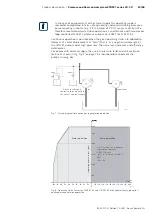
If the axis is to run exclusively in this operating mode, an analog signal within 

the range of +10 V to U

B

 is assigned to the pressure command value and used to 

deactivate the pressure controller (0...+10 V ≙ 0...100 % swivel angle).

The pressure transducer signal must be short-circuited or deactivated, because 

even actual pressure value signals of ≥8.0 V have an influence on or reduce the 

swivel angle output and hence the valve command value (actuating speed!).

A precondition for this is, however, that the electronics is set for an actual 

pressure value input “voltage” without raised zero point (e.g. 0 - 10 V, 0 - 20 mA). 

Otherwise, electronics set for an actual pressure value branch with raised zero 

point would change to an erroneous state when the pressure transducer signal is 

missing. 

u

u

u

u

u

u

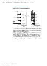
SYD_008

+10 V to 

UB


external

H

L

6c

4c

8c

10c

14c

16c

p

comm

Reference potential

p

act

 →0 to +10 V

0 to 5 V

SWA

comm 

→ -10 V to +10 V

Reference potential

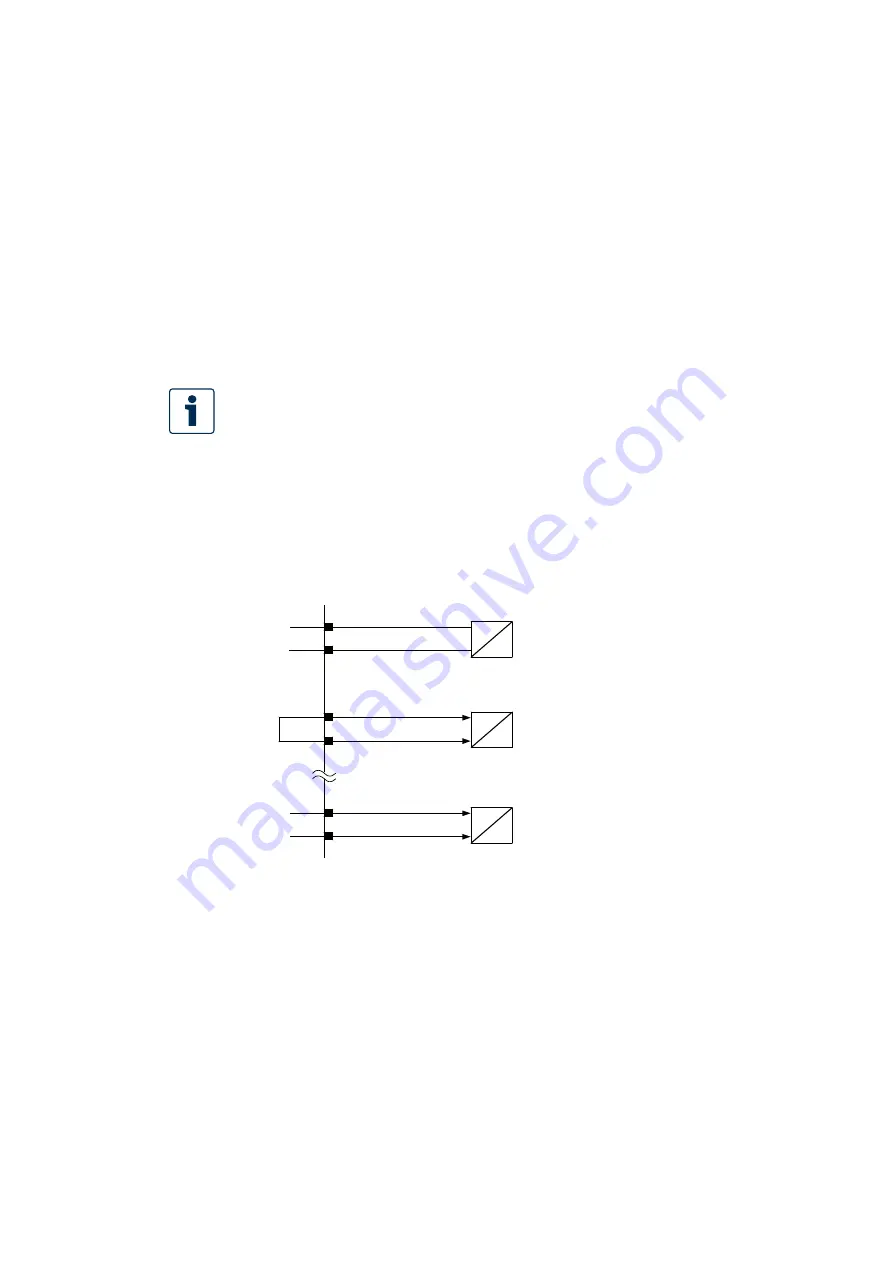
Fig. 5: Circuitry of control electronics VT 5041-3X for closed-loop swivel angle control

Summary of Contents for rexroth SYDFE1 2X Series

Page 1: ...ition 10 2021 replaces 07 2014 Pressure and flow control system SYDFE1 series 2X 3X with external control electronics VT 5041 3X SYDFE1 series 2X SYDFE1 series 3X with external control electronics VT 5041 3X Valid for the following types ...

Page 2: ...erification It must be remembered that our products are subject to a natural process of wear and aging This document as well as the data specifications and other information set forth in it are the exclusive property of Bosch Rexroth AG It may not be reproduced or given to third parties without its consent The cover shows an example configuration The product delivered may differ from the image on ...

Page 3: ...SYDFE1 16 5 3 Controller structure and basic operating modes 19 5 3 1 Swivel angle control 20 5 3 2 Pressure control 21 5 3 3 Power limitation optional with VT 5041 3X 3 21 5 4 Special operating modes 22 5 4 1 Regenerative operation 22 5 5 Operating pressure limits 25 5 5 1 Internal external pilot oil 25 5 6 Ambient conditions 27 5 6 1 Oil immersed applications 27 5 6 2 Ambient temperature 27 5 7 ...

Page 4: ...55 7 6 5 Connecting the swivel angle sensor 57 7 6 6 Connecting the solenoid of the proportional valve 58 7 6 7 Command values for pressure swivel angle and power limitation 58 8 Commissioning 59 8 1 Initial commissioning 60 8 1 1 Filling the SYDFE1 control system 60 8 1 2 Testing the hydraulic fluid supply 61 8 1 3 Performing a flushing cycle 61 8 1 4 Configuring switches and jumpers of the VT 50...

Page 5: ...ch Rexroth AG 78 13 3 Packaging 78 13 4 Materials used 78 13 5 Recycling 79 14 Extension and modification 79 15 Troubleshooting 80 15 5 1 Fault analysis 82 15 1 How to proceed for troubleshooting 84 15 2 Fault table 85 16 Technical data 88 17 Annex 89 17 1 List of addresses 89 17 2 Block circuit diagram of control electronics VT 5041 3X 90 17 3 Display and setting elements of control electronics V...

Page 6: ...essure flow control system SYDFE1 General operating instructions for axial piston units RE 90300 B Operating instructions Pressure and flow control system type SYDFE1 SYDFEE SYDFED SYDFEF component series 2X RE 30030 Data sheet Pressure and flow control system type SYDFE1 SYDFEE SYDFED SYDFEF component series 3X RE 30630 Data sheet Axial piston variable displacement pump A10VSO series 31 sizes 18 ...

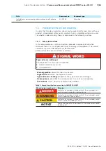
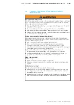
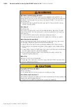
Page 7: ...e observed Safety instructions are structured as follows SIGNAL WORD Type and source of danger Consequences in case of non compliance Hazard avoidance measures Enumeration Warning symbol draws attention to a hazard Signal word identifies the degree of hazard Type and source of danger Specifies the type and source of danger Consequences describes the consequences in case of non compliance Precautio...

Page 8: ...xial piston variable displacement pump open circuit HM20 Pressure transducer IW9 Swivel angle sensor for the SYDFE1 control system SYDFE1 Pressure flow control system for external electronics SYDFE1 2X Pressure flow control system series 2X for external electronics and A10 VSO series 31 SYDFE1 3X Pressure flow control system series 3X for external electronics and A10 VSO series 32 VT DFP Pilot val...

Page 9: ...times Always include the required documentation when you pass the product on to third parties 2 2 INTENDED USE The product is electrical hydraulic equipment You may use the product as follows for the electrohydraulic pressure and swivel angle control of an axial piston variable displacement pump The product is intended exclusively for professional use and not for private usage Operation according ...

Page 10: ...the appropriate safety measures due to their professional training knowledge and experience as well as their understanding of the relevant conditions pertaining to the work to be undertaken Qualified personnel must observe the rules relevant to the subject area 2 5 GENERAL SAFETY INSTRUCTIONS Observe the valid regulations on accident prevention and environmental protection Observe the safety regul...

Page 11: ...stems Before beginning work Make sure that the drive motor cannot be switched on Make sure that all power transmitting components and connections electrical pneumatic hydraulic are switched off according to the manufacturer s instructions and are secured against being switched on again If possible remove the main fuse of the system Ensure that the system is completely hydraulically unloaded and de...

Page 12: ...gloves Risk of intoxication and injury Contact with hydraulic fluids can be damaging to your health e g eye injuries skin damage intoxication upon inhalation and swallowing Always check the lines for wear and damage before each commissioning When doing so wear protective gloves safety goggles and suitable working clothes If nevertheless hydraulic fluid comes into contact with the eyes or penetrate...

Page 13: ... must be intact 2 8 OBLIGATIONS OF THE MACHINE END USER The operation of installations systems and machines basically requires the implementation of a holistic IT security concept which is state of the art in terms of technology Accordingly Bosch Rexroth products and their properties must be considered as components of installations systems and machines for their holistic IT security concept Unles...

Page 14: ...nd that all seals and closing elements of plug in connections are correctly installed and not damaged Take care that no cleaning agents enter the hydraulic system Do not use cotton waste or linty cloths for cleaning Wear Wear may lead to malfunctions Carry out the prescribed maintenance work at the time intervals specified in the operating instructions Environmentally harmful hydraulic fluid Leaki...

Page 15: ...f delivery 1 control system SYDFE1 When delivered the following parts are mounted additionally 1 Transport protection for drive shaft end in the case of keyed shaft 2 Protective cover with mounting screws 3 Plastic plugs plug screws 4 Protective cover NG140 or plastic plug on pre load valve 5 The connection flange is closed operationally safe with a cover optionally on variant with through drive 2...

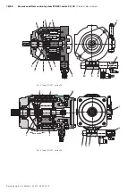
Page 16: ...ically controlled proportional valve 2 The proportional valve determines the position of the swashplate 1 by means of the actuating piston 4 The displaced flow is proportional to the position of the swashplate The counter piston 3 which is pre loaded by a spring 5 is permanently pressurized to pump pressure With a non rotating pump and depressurized actuating system the swashplate is held by the s...

Page 17: ...e swivel angle has reached the required value The movement of the valve spool against the force of the spring 10 is achieved by a corresponding increase in the electrical current through the proportional solenoid 8 A reduction of the swivel angle reduction in flow is achieved by connecting the actuating piston 4 from P A Since the introduction of A10VSO series 32 a so called pre compression volume...

Page 18: ...trol system SYDFE1 series 2X 3X Product description Bosch Rexroth AG Edition 10 2021 RE 30011 B Fig 2 Type SYDFE1 series 2X Fig 3 Type SYDFE1 series 3X P A T 5 3 7 8 9 10 2 4 1 6 1 4 100 100 5 3 14 P A T 10 9 8 7 6 2 Zero stroke ...

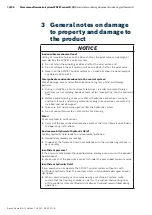
Page 19: ...r the above conditions NOTICE Cavitation of the pump Risk of damage to the pump in the case of systems with external supply To prevent damage to the pump provide a pressure relief anti cavitation valve for systems with external supply If a fault occurs during operation not during start up the motor must be switched off 5 3 CONTROLLER STRUCTURE AND BASIC OPERATING MODES The controller structure is ...

Page 20: ...be short circuited or deactivated because even actual pressure value signals of 8 0 V have an influence on or reduce the swivel angle output and hence the valve command value actuating speed A precondition for this is however that the electronics is set for an actual pressure value input voltage without raised zero point e g 0 10 V 0 20 mA Otherwise electronics set for an actual pressure value bra...

Page 21: ...ion If the axis is to operate in this mode an analog signal within the range from 10 0 V to UB can be assigned to the swivel angle command value and used to deactivate the swivel angle controller However for some applications it is advantageous to limit the permitted swiveling range of the pump by feedforwarding a suitable swivel angle command value However this command value must be sufficiently ...

Page 22: ...line closed irrespective of the command value received The feedforward of 0 bar via the pressure command value branch is not permitted for actuating systems with external supply In the case of systems with internal supply this is problematic only in the case of a step change from a high pressure to 0 because undershoots may occur 5 4 1 Regenerative operation Regenerative operation is a special ope...

Page 23: ...YDFE1 pump and at high pressures the noise level increases and efficiency deteriorates For pumps with external supply the use of a pressure relief and anti cavitation feature as shown in Fig Fig 7 on page 23 is indispensable to prevent the pump s running dry SYD_023 Q1 Q2 max 0 7 Q1 0 2 bar pmax Pressure relief anti cavitation valve required in the case of external supply Fig 7 Circuit diagram for...

Page 24: ... of 0 10 V this command value is interpreted by the control electronics so that the swivel angle of the pump is controlled within the swiveling range from 0 displacement to 100 displacement During regenerative operation depending on the pump combination a swivel angle command value of up to 70 or 7 V has to be provided If the higher level control is not able to generate the command value range of ...

Page 25: ...s can occur with this version Operation is also possible at pressures higher than approximately 12 bar but dynamics is restricted within the range below 20 bar This minimum pilot pressure level ensures that the pump can respond to the electrical swivel signal at any time When the consumer line is blocked the smallest achievable steady state swivel angle is the zero stroke angle For applications in...

Page 26: ... within the range of 100 change in the direction of displacement In the following situations the pump swivels to position 100 motor operation in an uncontrolled manner when the enable of the control electronics is missing or an error message of the control electronics exception J1 set see page 63 or in the de energized state of the control electronics This can lead to cavitation and damage to the ...

Page 27: ... 5 6 2 Ambient temperature The permissible maximum ambient temperature for SYDFE1 control systems is 70 C at the pump and 50 C at control electronics VT 5041 3X We recommend the installation within a ventilated area with moved ambient air e g in the air flow of an electric motor 5 7 NOTES ON THE SELECTION OF HYDRAULIC FLUIDS The SYDFE1 control system is designed for operation with hydraulic fluids...

Page 28: ...evving speed is always higher than the tank temperature However the temperature must not exceed 90 C at any point in the system If the conditions described above cannot be complied with due to extreme operating parameters or high ambient temperatures please consult us The finer the filtration of the hydraulic fluid the better is the achieved cleanliness class which in turn prolongs the service lif...

Page 29: ...level of the hydraulic system as a whole Further information can be found in data sheet RE 50142 5 9 SHAFT VARIANT The SYDFE1 control system is available with keyed or splined shafts When compared with the keyed shaft the splined shaft is not only advantageous with regard to its degrees of freedom during assembly and operation but also due to its increased torque load carrying capacity and its sta...

Page 30: ... safety relevant interventions must be made by the higher level control e g switching the drive motor OFF closing the shut off valves The enable for the control electronics is granted by applying 24 V to switching input 26c This activates the output stage of the VT 5041 3X i e the pilot valve The presence of the enable is signaled by LED En on the front panel The following options are provided for...

Page 31: ...put 2c signals a trouble free state with a 24 V level When a fault is recognized this is output as collective fault by a signal level of 0 V at 2c At the front panel of the control electronics a fault message is signaled by LED Err Also a missing enable will lead to the generation of a fault message Causes for fault messages are described in chapter 15 Troubleshooting page 80 5 11 5 Signaling of t...

Page 32: ...iter on the front panel On control electronics with power limitation test jack 8 is used to adjust measure the power limit value Table 7 Test jacks Assignment of test jacks Test jack 1 Pressure command value 0 10 V Test jack 2 Actual pressure value 0 10 V Test jack 3 Swivel angle command value 10 V 10 V 100 100 Test jack 4 Actual swivel angle value 10 V 10 V 100 100 Test jack 5 Valve command value...

Page 33: ... natural frequency Overriding closed position or velocity control loop 5 11 9 Power limitation VT 5041 3X 3 only In the case of electronics variants with power limitation a limiting value can be set by means of a potentiometer Alternatively a limit value can be provided externally to contacts 18c 20c if jumper J2 is set in position 2 3 0 100 0 100 Power Actual pressure value Max flow Fig 11 Power ...

Page 34: ...f provided has to be connected The master controls both pressure and swivel angle in accordance with the externally provided command values and passes its actual swivel value SWAact on to the slave pumps as swivel angle command value SWAcomm This ensures smooth and synchronous swiveling of the pumps Consequently the slave pumps operate only under swivel angle control which is the reason why in thi...

Page 35: ...he proposal shown here both swivel angle and pressure control are possible with the slave pump For the master slave operating mode the signal pcomm II must be set to maximum 10 V If closed loop pressure control is to be realized also in the master slave operating mode only the pressure transducer of the master is evaluated for controlling purposes If hydraulically separated operation should be pos...

Page 36: ...ow command value to a low value e g 10 When a pre load valve is used the pump with the pre load valve should preferably be the master pump Only in conjunction with VT 5041 3X 3 Fig 13 At low operating pressures the flow command value which has been provided by the control is withdrawn from the slave pump via a changeover contact suitable for small signal voltages or alternatively a wear free analo...

Page 37: ... short circuited 5 12 1 Switch on sequence of electronics hydraulics Due to various monitoring routines implemented in the electronic assemblies fault messages may be generated in the case of an unfavorable order of switching on These error messages cause uncertainties although they have no real cause of fault In principle it is valid that all SYDFE1 pump systems that are provided exclusively with...

Page 38: ...he figure below shows an example of a SY2DFEE nameplate BCS S SFI SJDIUVOH 3 3FYSPUI 4 4 9 3 3 BEF JO FSNBOZ 3 3 Material short text Production job order no Designation of origin Word mark Material number Date of production Plant Indication of direction of rotation Production location Fabrication number Fig 15 Nameplate For queries with regard to the pump combination you must indicate the material...

Page 39: ...control system SYDFE1 control systems of a low weight can be transported manually if required the weight for brief lifting should not exceed 15 kg for women and 25 kg for men CAUTION Risk of health damage Lifting heavy SYDFE1 control systems involves the risk of health damage When carrying the control system apply suitable techniques for lifting lowering and relocating or use suitable lifting gear...

Page 40: ...w Place the lifting strap around the SYDFE1 control system in such a way that it neither passes over the attached parts e g valves nor such that the SYDFE1 control system is hung from attached parts see Fig 17 CAUTION Risk of injury During transport with a lifting device the control system can fall out of the lifting strap and cause injuries Hold the control system with your hands to prevent it fr...

Page 41: ...control system inspected by your responsible Rexroth Service partner Should you have questions regarding spare parts contact your Rexroth Service partner responsible for SYDFE1 control systems see chapter 10 5 Spare parts page 75 for further information If a demounted SYDFE1 control system is to be stored it must be preserved against corrosion for the duration of storage The following instructions...

Page 42: ...ll limits specified in the data sheet regarding temperature viscosity cleanliness of the hydraulic fluid Make certain that the case of the SYDFE1 control system is filled with hydraulic fluid during commissioning and in operation This is also to be observed following relatively long standstill periods as the SYDFE1 control system may empty via the hydraulic lines To achieve favorable noise values ...

Page 43: ...on NOTICE Insufficient hydraulic fluid Risk of damage or destruction of the rotary group Each control system type has its optimum filling orientation Only this orientation allows complete filling of the case which is the reason why this orientation must be adhered to during commissioning For re commissioning this orientation should be complied with as far as possible In the following we distinguis...

Page 44: ...itions that always the higher of drain ports L or L1 is piped Moreover the distance between the end of installed pipes and the minimum oil level must not be shorter than the specified minimum distance immersion depth E When installing suction and case drain lines take care that the routing is straight and short and has as few bends as possible When the system is at rest the lines drain automatical...

Page 45: ...ance of the case drain line Δpi f diameter length Here the flow resistance at the case drain fitting on the pump case plays a subordinate role The Δpi value can only be improved by a larger nominal width of the case drain line Generally the following must be observed Each pump should preferably be piped with a separate case drain line Direct the case drain fluid in the case chamber via the highest...

Page 46: ...code with the details on the order confirmation If the material number for the SYDFE1 control system is not identical with that on the order confirmation contact Rexroth Service for clarification see chapter 10 5 Spare parts on page 75 for address 3 Before installing the SYDFE1 control system completely empty it to prevent mixing with the hydraulic fluid used in the system 4 Check the direction of...

Page 47: ...h a threaded bore Use this threaded bore to mount the coupling element on the drive shaft Refer to the installation drawing for the dimensions of the threaded bore 2 Make sure that the installation location is clean and free from dirt and foreign particles 3 Positively clamp the coupling hub on the drive shaft or ensure permanent lubrication of the drive shaft This prevents the formation of fricti...

Page 48: ...nauthorized resetting by means of protective caps Removing protective caps will void the warranty If you need to modify the setting please contact the responsible Rexroth Service for address see chapter 10 5 Spare parts on page 75 For the variant with through drive mount the auxiliary pump in accordance with the instructions of the pump manufacturer 7 5 CONNECTING THE SYDFE1 CONTROL SYSTEM HYDRAUL...

Page 49: ...rts Observe the following notes when routing suction pressure and case drain lines See to it that the suction line pipe or flexible hose is as short and straight as possible The line cross section of the suction line is to be dimensioned so that the pressure in the suction port does not fall below the minimum permissible value and the maximum permissible pressure is not exceeded Observe air tightn...

Page 50: ...ed using suitable plug screws The installation drawing contains the dimensions of all connections and ports on the SYDFE1 control system Also observe the instructions provided by the manufacturers of the other hydraulic components when selecting the required tools 4 Make sure that the cap nuts are correctly tightened on the fittings and flanges observe tightening torques Mark all checked fittings ...

Page 51: ...ounting screws and plug screws For all threaded holes use a male stud from the same system of units and of the correct size Table 9 Tightening torques of threaded holes and plug screws Thread size of ports Max permissible tightening torque of threaded holes MGmax Required tightening torques for plug screws MV A F hexagon socket M10x1 DIN 3852 30 Nm 12 Nm 5 mm M12x1 5 DIN 3852 50 Nm 25 Nm 6 mm M14x...

Page 52: ... electronic components Generally the following is valid Use low capacitance cables according to the safety regulations of the German VDE or national electrical safety regulations of your country Whenever possible establish the cable connections without intermediate terminals Select only cables that have the actually required number of wires avoid superfluous wires The installation of electromagnet...

Page 53: ...ystem must however be ordered separately In terms of signals the sensors have to be distinguished as follows Sensors with current interface Sensors with voltage interface Here the usual signal limits are between 0 20 mA or 0 10 V respectively Within these limits there are further modifications that depend on required options such as monitoring for cable break From a technical point of view the eff...

Page 54: ... a 2 wire current interface and can be connected to control electronics VT 5041 3X as shown below The voltage supply for the pressure transducer must be provided in accordance with the data sheet For more detailed information about the pressure transducer HM20 C see data sheet RE 20272 Recommended cable type LiYCY 2 x 0 25 mm Fig 23 Connection pattern for pressure transducer HM20 C Pressure transd...

Page 55: ...tronics VT 5041 3X can sense the position transducer signal according to the specification of the VT 5041 2X without requiring a different sensor cable Make certain that jumper J8 is set on control electronics VT 5041 3X VT5041 2X Fig 25 Connection pattern of the valve position transducer in conjunction with VT5041 2X old systems The following is valid for all new systems In the case of cable leng...

Page 56: ...ray ws white bn brown gb yellow gn green Jumper J8 ON VT5041 3X Fig 26 Cabling for cable lengths up to 50 m If distances of 50 m or greater must be covered we recommend that twisted pair cables be installed In this case jumper J8 must not be set on control electronics VT 5041 3X Recommended cable type LiYCY TP 2 x 2 x 0 25 mm Shield Valve position transducer Fig 27 Cabling in case of cable lengths...

Page 57: ...ntrol electronics VT 5041 2X it must in any case be checked in advance that there is no connection between pin 12a and 26a Moreover connection 12a of control electronics VT 5041 3X must not be connected to a further connection Fig 28 Connection for swivel angle sensor Fig 29 Connection for clockwise rotating pump Fig 30 Connection for counter clockwise rotating pump to swivel angle controller R8 Z...

Page 58: ...limitation General notes The command values for pressure and swivel angle are provided as analog variables within the voltage range of 0 10 V this corresponds to 0 100 of the physical range of values Command values may only be passed on using appropriate contacts that are suitable for currents 1 mA The use of shielded cables is recommended connect shield of the signal cable to 26a Command value fo...

Page 59: ...an injure you Only commission a completely installed product NOTICE Loss of protection class due to missing seals and plugs Liquids and foreign particles may penetrate and damage the product Before commissioning make sure that all seals and plugs of plug in connections are tight Ingress of dirt Damage to the SYDFE1 control system Contamination of the hydraulic fluid results in wear and malfunction...

Page 60: ...junction with commissioning of the SYDFE1 control system observe the basic safety instructions and intended use provided in chapter 2 Safety instructions on page 9 8 1 1 Filling the SYDFE1 control system NOTICE Spilled hydraulic fluid Discharging or spilling hydraulic fluid while filling the SYDFE1 control system can lead to environmental pollution and contamination of the groundwater When filling...

Page 61: ...upplied with sufficient hydraulic fluid For this reason the supply of hydraulic fluid must be ensured at the start of the commissioning process When you test the hydraulic fluid supply constantly monitor the noise generation and check the hydraulic fluid level in the tank If the SYDFE1 control system becomes louder cavitation or the case drain fluid flows out with bubbles this is an indication tha...

Page 62: ... B 0 20 mA ON ON OFF OFF OFF OFF ON ON C 4 20 mA ON ON OFF OFF ON ON OFF OFF V factory setting Case drain compensation is used for compensating for leakage of the pump and can be set to the following values by means of jumpers J6 and J7 on control electronics VT 5041 3X Table 11 Adjustment of case drain compensation Case drain compensation Jumper J6 J7 OFF OFF OFF 4 OFF ON 6 ON OFF 10 ON ON Factor...

Page 63: ...led by the fault signal outputs and at the same time the activation of the pilot valve is interrupted This ensures that the pilot valve takes a defined position and the pump with internal pilot supply swivels to the zero stroke position With control electronics VT 5041 3X the shutdown of the valve output stage can be prevented by means of a jumper To this end jumper J1 must be set Table 14 Activat...

Page 64: ... exclusively under closed loop swivel angle control Version with power limitation VT 5041 3X 3 With the variant of the VT 5041 3X with power limitation the analog value is taken as power command value For further notes on power limitation please read chapter 5 11 9 Power limitation VT 5041 3X 3 only on page 33 If control electronics VT 5041 3X is installed as replacement for VT 5041 2X in an exist...

Page 65: ...is applied The red LED Err fault must not be ON If this state is not reached a fault must have occurred Possible faults The green LED Ub is OFF Check the supply voltage Check fuse F1 The red LED Err fault is ON The enable contact must be made i e En is ON Measure the actual pressure value at test jack 2 must be ca 0 V In the case of a negative voltage of less than ca 1 V or voltages greater than c...

Page 66: ... These values are valid when you use our standard pressure transducer with a measuring range of 0 315 bar In this state the control electronics VT 5041 3X signals a fault excessive control deviation When the electronics works properly the error message disappears when the motor is switched on control error now equal to zero Before further commissioning let the hydraulic oil warm up to operating te...

Page 67: ... the operating pressure The operating pressure is the pressure level that the pump system is to generate as maximum value in the system The control electronics converts the signal level of the pressure transducer connected to the pump system into the normalized level of 0 10 V and passes this actual pressure value on to the pressure controller The converted actual pressure value can be measured at...

Page 68: ...ommand value V In the case of actual pressure value adjustment the actual pressure value is normalized to the operating pressure With the factory setting the control electronics VT 5041 3X converts the signal of the pressure transducer internally into the range of 0 10 V To change the signal range gain of the actual pressure value use potentiometer R2 front panel of control electronics VT 5041 3X ...

Page 69: ...able 15 Volume adjustment Volume adjustment of pressure controller td OFF Switch S3 1 2 3 5 0 OFF OFF OFF 7 5 OFF ON OFF 10 ON ON OFF 15 ON OFF ON 20 OFF ON ON 25 ON ON ON Pressure controller td ON Switch S3 4 5 6 12 5 OFF OFF OFF 30 OFF ON OFF 45 ON ON OFF 60 ON OFF ON 75 OFF ON ON 90 ON ON ON Under normal conditions it is not required to change the P component of the pressure controller However ...

Page 70: ...ngle value and set it to 10 V 0 01 V corresponds to maximum stroke by means of potentiometer R9 3 In some cases the pump will not swivel to the limit stop maximum value For this reason briefly switch the motor on then switch off again wait until the pump has swiveled out and then measure the actual swivel angle value If a higher voltage is measured correct the value Repeat this procedure several t...

Page 71: ... be ensured that the SYDFE1 control system was installed into the machine or system in accordance with the plans and drawings Use the swivel angle indicator to check whether the SYDFE1 control system correctly swivels in and out during operation The position of the swivel angle indicator and the assignment of the swiveling direction to the direction of rotation and control can be found in the asso...

Page 72: ... the operating temperature during the running in phase Reduce the loading pressure speed of the SYDFE1 control system if impermissible operating temperatures and or viscosities occur Bearings and sliding surfaces are subject to a running in phase Increased friction at the start of the running in phase results in increased heat generation which decreases with increasing operating hours The volumetr...

Page 73: ...ngs with suitable protective caps devices Check that all seals and plugs of the plug in connections are securely seated to ensure that no moisture can enter the SYDFE1 control system during cleaning Use only water and if necessary a mild detergent to clean the SYDFE1 control system Remove external coarse dirt and keep sensitive and important parts like solenoids valves and indicators clean 10 2 IN...

Page 74: ...mmend changing the hydraulic fluid at least once a year or every 2000 operating hours whichever occurs first or having it analyzed by the hydraulic fluid supplier or a laboratory to determine its suitability for further use The service life of the SYDFE1 control system is limited by the service life of the built in bearings The service life can be requested on the basis of the load cycle from the ...

Page 75: ...e principle and senses the mechanical stroke of the pump without wear In the case of faults in swivel angle sensing both the coil body and the mechanical parts are easy to replace If the settings of control electronics VT 5041 2X were not changed matching of the coil body is limited to mechanical clamping fixing preferably in zero stroke operation while controlling the electrical zero point on the...

Page 76: ...28 and 45 45 Nm Size 71 55 Nm Sizes 100 140 and 180 100 Nm After having mounted the pre load valve connect the high pressure and case drain oil pipes as described in chapter 7 3 Installation positions and piping of SYDFE1 systems on page 43 During re commissioning bleed the pre load valve Notes on the bleeding procedure can be found in chapter 8 1 8 Bleeding the pre load valve on page 67 11 Decomm...

Page 77: ...ck that the SYDFE1 control system has cooled down sufficiently so that it can be demounted without any risks NOTICE Spilled or discharged hydraulic fluid Environmental damage and contamination of the groundwater When filling in and changing the hydraulic fluid always place a catch pan under the SYDFE1 control system Observe the information in the safety data sheet for the hydraulic fluid and the i...

Page 78: ...riate foreign substances or third party components Hydraulic valves have to be drained before being returned The components have to be sent carriage paid to the following address Bosch Rexroth AG Service Industriehydraulik Bürgermeister Dr Nebel Straße 8 97816 Lohr am Main Germany 13 3 PACKAGING Upon request reusable systems can be used for regular deliveries The materials for disposable packaging...

Page 79: ...ans of special separation procedures 14 Extension and modification The SYDFE1 control system may only be converted or extended in the cases described below using genuine Rexroth SYDFE1 components Other conversions or extensions also the readjustment of lead sealed adjustment potentiometers render the warranty void The replacement of a component with a component of identical design is described in ...

Page 80: ...owing Voltage supply available U 21 35 V Check fuse F1 This LED signals a collective fault or missing enable The fault signal can also be measured at pin 2c of the female multi point connector and can be used for signaling this to a higher level control The following is valid here 0 V fault 24 V no fault The fault signal refers to a collective fault and is composed of the following individual faul...

Page 81: ...individual faults nor the collective fault are saved and they always reflect the momentary state If a loose connection at a plug in connector of the swivel angle transducer IW9 results in the temporary detection of a fault this individual fault will trigger the issue of a fault signal Depending on the configuration of jumper J1 the following will happen J1 ON i e shutdown of the valve output stage...

Page 82: ...which can be measured at test jack 2 is monitored for the permitted range The permitted range is between 0 5 V and 11 5 V Possible faults can be an interrupted signal cable missing voltage supply to the sensor or an incorrectly adapted actual pressure value signal Actual pressure value 0 5V Check cabling and voltage supply to the pressure transducer Correct zero point of the actual pressure value ...

Page 83: ...ged in on the valves Switch voltage off Remove control electronics VT 5041 3X from the rack Female multi point connector 28c to 30c ca 2 4 Ohm solenoid Female multi point connector 4a to 6a ca 103 Ohm position transducer Female multi point connector 8a to 6a ca 115 Ohm position transducer This monitoring function is active only when jumper J9 is set ON The monitoring feature which was newly added ...

Page 84: ...f Activate the motor fuse Switch the pump on 15 1 HOW TO PROCEED FOR TROUBLESHOOTING Always work systematically and purposefully even when under time pressure Random and imprudent disassembly and changing of settings can in the worst case scenario result in the inability to determine the original cause of error First obtain a general overview of how your product works in conjunction with the entir...

Page 85: ...her notes see page 63 Defect or short circuit of auxiliary voltages on the control electronics Contact Rexroth Service Humming noise in the pressure control or fluctuations in pressure flow Air cushion around the sensor Bleed control system pre load valve see 8 1 8 on page 67 and pipes completely Problem with the cable shield Connect shield to ground Unfavorable place of installation mounting tech...

Page 86: ...ctions of the coupling or fitting manufacturer Air in the pump or in the pre load valve Bleed pump and pre load valve Wear mechanical damage to the control system Replace control system contact Rexroth Service No or insufficient pressure 4 bar Faulty mechanical drive e g defective coupling Machine or system manufacturer Hydraulic fluid not within the optimum viscosity range Use suitable hydraulic ...

Page 87: ...e equal and can be regulated Adjust pressure command value and or actual pressure value see page 68 Replace pressure transducer Replace control electronics VT 5041 3X Pressure transducer defective not connected Diagnostics Measure signal from PT and compare with indication on the pressure gauge Connect pressure transducer correctly replace Insufficient flow Pressure controller active Increase pres...

Page 88: ...opens Diagnostics Pipe to the tank heats up Pressure must be lower than the cracking pressure of the pre load valve Keep overshoots and pressure pulsation to a minimum Malfunction of pressure pilot valves e g high pressure relief valve pressure cut off pressure controller Contact Rexroth Service Control system worn out Replace control system contact Rexroth Service 16 Technical data The technical ...

Page 89: ...ail service boschrexroth de Outside Germany you will find service subsidiaries in your vicinity on the Internet at www boschrexroth com Email support automation boschrexroth com Bosch Rexroth AG Zum Eisengiesser 1 97816 Lohr am Main Germany Phone 49 0 9352 40 30 20 Email my support boschrexroth com The addresses of our sales and service network and sales organizations can be found at www boschrexr...

Page 90: ...T 5041 3X on pageSeite 92 Meaning of the test jacks display and setting elements potentiometers on the front panel see data sheet 40242 page 9 Reference Reference Reference Reference Pressure controller OFF Master slave Version VT5041 3X 1 0 or 2 0 SWAACT master or Power limit 0 10 V Enable Shield System ground Version VT5041 3X 3 0 Power limit Adjustment Single pump combination Leakage com pensat...

Page 91: ... angle value Collective fault compatible with VT 5041 2X J1 OFF Error actual valve value Primary Secondary Error actual swivel angle value J8 ON compatible with VT 5041 2X factory setting Connection with twisted pair cable J8 off Diagnostic LEDs on the printed circuit board v com Excessive permanent control error v act Error actual valve value out of range p act Actual pressure value error SWA act...

Page 92: ...ON OFF 4 0 OFF OFF ON 3 0 OFF ON ON 2 4 ON OFF ON 2 0 ON ON ON 7 Selection for analog input at pin 18c Jumper J2 bridge Actual swivel angle value of master 1 2 External power limitation 2 3 11 Volume adjustment pressure controller Input of switch TD OFF Switch S3 Input of switch TD ON Switch S3 1 2 3 4 5 6 5 0 l OFF OFF OFF 12 5 l OFF OFF OFF 7 5 l OFF ON OFF 30 0 l OFF ON OFF 10 0 l ON ON OFF 45 ...

Page 93: ...Control electronics VT 5041 3X Block diagram 90 Functions 30 Controller structure 19 Control mode Message 31 Conversion 79 Coupling 47 D Damage to property general notes 14 Data sheet 6 Decommissioning 76 Demounting 77 Demounting 77 Preparing 77 Device description 16 Dimensions 39 Connections 46 Direction of rotation 46 Display and setting elements of control electronics VT 5041 3X 92 Disposal 78 ...

Page 94: ...unting orientation 53 Place of mounting 53 Product description 16 Pulsation damper 29 Q Qualification of personnel 10 R Recommissioning after downtime 72 Regenerative operation 22 Replacement of components 75 Required documentation 6 Ring screw 39 Running in phase 72 S Safety instructions 9 general 10 product and technology related 11 Signal word 7 Scope of delivery 15 Setting swivel angle 100 70 ...

Page 95: ... flow control system SYDFE1 series 2X 3X 95 96 V Valve command value monitoring 63 Valve shutdown in the event of a fault 63 Valve zero point checking and correcting 66 Viscosity 27 Viscosity limits 27 Volume adjustment 69 W Warranty 48 60 Weights 39 Z Zero stroke operation 22 ...

Page 96: ...ch Rexroth AG Industrial Hydraulics Zum Eisengiesser 1 97816 Lohr a Main Germany Phone 49 0 9352 40 30 20 my support boschrexroth com www boschrexroth com Subject to revision Printed in Germany RE 30011 B ...

Reviews: