RE 30011-B, Edition 10.2021, Bosch Rexroth AG
Product description |
Pressure and flow control system SYDFE1 series 2X, 3X
37/96
For both control electronics:
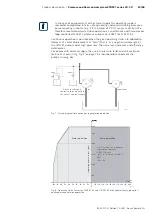
At the point in time when the master/slave operating mode is activated, the
hydraulic short-circuit valve (connection of the previously separated pressure
circuits) can be activated as well. The activation of this valve may have to be
delayed depending on whether this would improve the system characteristics in
the changeover process.
In the master/slave operating mode it is also useful that the control keeps the two
swivel angle command values for the master and the slave pump synchronized in
order that striking differences in the signal level are prevented when the swivel
angle command value source for the slave pump is switched (from actual swivel
angle value of the master pump back to the control output).
The pressure command value of the slave pump should be set to the same level
as that of the master pump before the slave pump is changed over to individual
operation (jerk-free changeover).
All the analog inputs that are not used, e.g. actual pressure value input in the case
of flow control, must be connected to 0 Volt.
In contrast to this, differential amplifier inputs that are not used may also be
short-circuited.
5.12.1 Switch-on sequence of electronics/hydraulics
Due to various monitoring routines implemented in the electronic assemblies, fault
messages may be generated in the case of an unfavorable order of switching on.
These error messages cause uncertainties, although they have no “real” cause of
fault.
In principle, it is valid that all SYDFE1 pump systems that are provided exclusively
with internal pilot oil supply automatically swivel to the operationally safe zero
stroke position in the event of a power failure, missing enable or active fault
message (except, “J1” is set, see page 63). However, a precondition for zero
stroke is a minimum pressure of 8...12 bar, which the pump has to build up as
pilot pressure. This can always be ensured, when no oil can flow away from the
pump output (e.g. actuator line hydraulically blocked).
▶ Observe the special case of suspended loads!
Observe the following activation sequence when
switching on
the analog SYDFE1
electronics:
1.
Voltage supply of the electronics on
2.
“Enable” signal (VT 5041-3X) when the el. motor starts up and suppression
of fault messages. After the star/delta changeover the error message can be
evaluated.
3.
Open check valve (if provided)
The
switching off sequence
is as follows:
1.
Command value provision: α
comm
= 5 % and p = 10 bar
2.
Close check valve (if provided)
3.
Suppress error message
4.
Switch el. motor off
Deactivating master/
slave operation
Connection of unused
electrical signal inputs
General information

