66/96
Pressure and flow control system SYDFE1 series 2X, 3X
| Commissioning
Bosch Rexroth AG, Edition 10.2021, RE 30011-B
• The voltage symmetry of the high-response valve’s internal voltage may be
outside the limit value. You can check the voltage at connections 24a (+15 V)
and 20a (-15 V).
After having detected the fault:
▶ Switch off supply voltage
▶ Eliminate fault
▶ Switch on supply voltage and grant enable
▶ Provide command values for (e.g. +1.5 V) and swivel angle (e.g. +2.5 V).
▶ At test jack 1, +1.5 V have to be present, at test jack 3, +2.5 V. If not, inspect
the cabling of the command value source.
When adjusting the zero point, always see to it that the hydraulic system is
depressurized at the place of measurement of the pressure transducer!
▶ Check the voltage at test jack 2: 0 V ±50 mV
▶ If required, calibrate using potentiometer R1 (at the front)
8.1.6 Switching on the drive motor of the pump
1.
Close all directional valves.
2.
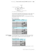
Before switching the motor on, apply the following command values to control
electronics VT 5041-3X:
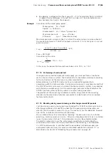
Pressure command value (p
comm
)
=
1.0 V ≙ 31.5 bar
Flow command value (SWA
comm
) =
2.0 V ≙ 20 %
These values are valid when you use our standard pressure transducer with a
measuring range of 0...315 bar.
In this state, the control electronics VT 5041-3X signals a “fault“ (excessive control
deviation). When the electronics works properly, the error message disappears
when the motor is switched on (control error now equal to zero).
▶ Before further commissioning, let the hydraulic oil warm up to operating
temperature.
▶ For initial commissioning, limit the pressure to max. 50 bar.
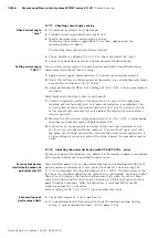
8.1.7 Checking and correcting the valve zero point
▶ All directional valves must be closed, no oil flow permitted!
▶ Provide a swivel angle command value of ≥ 5 V (test jack 3 ≥ +5 V)
▶ Set an operating pressure of ca. 100 bar by increasing the pressure command
value (read off from the pressure gauge)
▶ The correct setting of the valve zero point can be measured between test jacks
1 and 2. At an operating pressure of 100 bar, a voltage value of 0 V ±0.05 V
must be measurable at test jacks 1 and 2.
If the control error is greater (caused by, for example, differing cable lengths),
correct the value by adjusting potentiometer R6 at the front panel.
Adjust R6 so that a voltage of 0 V is measured between test jacks 1 and 2.
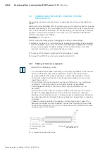
Check connection of
command values for
pressure and swivel
angle
Check the zero point of
the pressure transducer

