8/96
Pressure and flow control system SYDFE1 series 2X, 3X
| About this documentation
Bosch Rexroth AG, Edition 10.2021, RE 30011-B
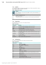
1.3.2 Symbols
The following symbols indicate notices which are not safety-relevant but increase
the comprehensibility of the documentation.
Table 3: Meaning of the symbols
Symbol Meaning
If this information is disregarded, the product cannot be used or operated in an
optimum manner.
▶
Individual, independent action
1.
2.
3.
Numbered instruction:
The numbers indicate that the actions must be carried out one after the other.
1.3.3 Designations
The following terms are used in this documentation:
Table 4: Designations
Designation
Meaning
A10VSO
Axial piston variable displacement pump, open circuit
A4VSO
Axial piston variable displacement pump, open circuit
HM20
Pressure transducer
IW9
Swivel angle sensor for the SYDFE1 control system
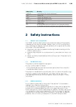
SYDFE1
Pressure/flow control system for external electronics
SYDFE1-2X
Pressure/flow control system, series 2X, for external electronics and
A10 VSO series 31
SYDFE1-3X
Pressure/flow control system, series 3X, for external electronics and
A10 VSO series 32
VT-DFP
Pilot valve for SYDFE1
VT 5041-3X
External control electronics for SYDFE1
1.3.4 Abbreviations
The following abbreviations are used in this documentation:
Table 5: Abbreviations
Abbreviation
Meaning
PT
P
ressure T
ransducer
EMC
E
lectro
m
agnetic
c
ompatibility
GND
Ground
NG
N
enn
g
röße (size)
p
Pressure (symbol)
P
Power
PCV
P
re
C
ompression
V
olume
p
Diff
Control difference between pressure command value and actual
pressure value
PE
P
rotective
E
arth
p
act
Actual pressure value
p
comm
Pressure command value
RE
R
exroth document in
E
nglish language


