RE 30017-B, Edition 11.2021, Bosch Rexroth AG
Product description |
SYDFED-2X, SYDFED-3X, SYHDFED-1X
33/96
5.9
MASTER/SLAVE OPERATION
SYD_022
MASTER
SLAVE
1
SLAVE
n
p,Q
p
u(i)
Druck-
Schwenkwinkel
Sollwerte
( soll)
( soll)
( ist oder aktuelle Menge)
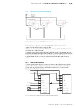
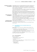
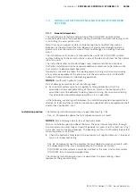
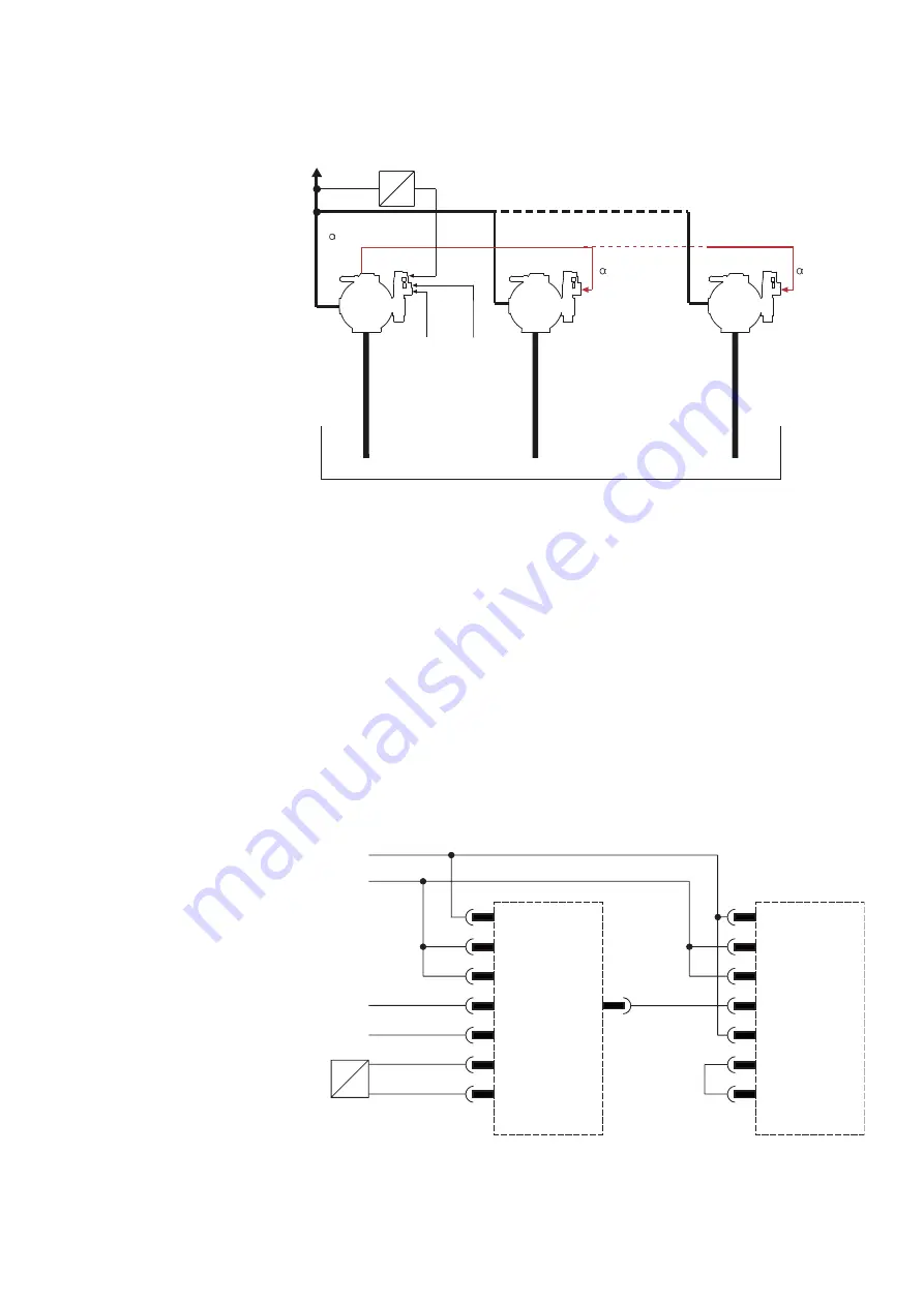
Fig. 12: Hydraulic coupling of SY(H)DFED control systems
Theoretically, an optional number of SY(H)DFED control systems can be
hydraulically coupled to achieve greater flows.
In this case, it is just required to determine a master pump to which the pressure
transducer has to be connected.
The master then controls both, pressure and swivel angle, in accordance with the
externally provided command values and passes its actual swivel angle value on to
the slave pumps. Based on this input the slave pumps calculate their own swivel
angle command value. This ensures smooth and synchronous swiveling of the
pumps.
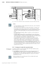
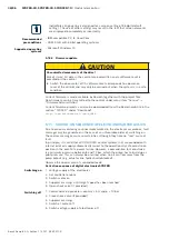
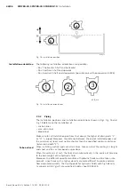
5.9.1 Circuitry of SY(H)DFED
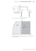
The two figures below show the circuitry for master/slave operation with analog
signals. Alternatively, master/slave operation can also be set up via a field bus
system and the machine control. For detailed information, see the functional
description of the firmware used.
P
U
1 U
B
2 L0
4 M0
5 α
comm
α
act
6
7 p
comm
10 p
act
- high
11 p
act
- low
Master
α
comm
(I)
p
comm
(I)
U
B
0 V
1 U
B
2 L0
4 M0
5 α
comm
7 p
comm
10 p
act
- high
11 p
act
- low
Slave
Fig. 13: Circuitry of SY(H)DFED for master/slave operation (analog)

