RE 30017-B, Edition 11.2021, Bosch Rexroth AG
Installation |
SYDFED-2X, SYDFED-3X, SYHDFED-1X
45/96
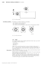
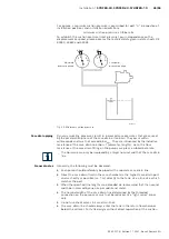
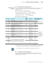
For pumps, a minimum suction pressure is prescribed for port “S” irrespective of
installation positions and installation orientations:
minimum suction pressure ≥ 0.8 bar abs.
To establish the suction pressure (inlet pressure) p
abs
in dependence on the
displacement or speed, please observe the technical data given in data sheets RE
30030, 30630 and 30035.
SYD_017
0
1
2
3
0,8 abs.
-1
0
1
2
-0,2
Standard
pressure gauge
Absolute
pressure gauge
Fig. 20: Minimum suction pressure
Dynamic swiveling processes result in increased case pressures that are caused
by the acceleration phase of the case drain oil column. They occur within
milliseconds and must not exceed 6 bar
abs.
. They are influenced by the inductive
resistance of the case drain line (Δpi = f (diameter, length)). Here, the flow
resistance at the case drain fitting on the pump case plays a subordinate role.
The Δpi value can only be improved by a larger nominal width of the case drain
line.
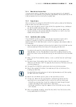
Generally, the following must be observed:
▶ Each pump should preferably be piped with a separate case drain line.
▶ Direct the case drain fluid in the case chamber via the highest case drain port
and as shortly as possible (ca. 1 m) directly to the tank. Use a line size, which
matches the port.
▶ When the specified line lengths are exceeded we recommend that the nominal
width be increased by one size per additional meter.
▶ The nominal width of the case drain line determined by the threaded
connection on the pump case must not be reduced. Use “light series” pipes
only.
▶ Do not use check valves in case drain lines.
▶ The case drain line should always enter the tank in the return flow chamber
below the oil level. For tank designs without direct separation of the suction
Case drain piping
General notes

