RE 30017-B, Edition 11.2021, Bosch Rexroth AG
Installation |
SYDFED-2X, SYDFED-3X, SYHDFED-1X
53/96
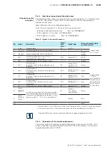
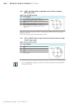
7.6.2 Electrical connection of the pilot valve
The following table shows the pinout of the central connector 11 + PE pilot valve
VT-DFPD. The column “code” refers to the cable kit that can be ordered as
optional accessories.
Bosch Rexroth offers the followingcable kits:
Type: Plug-in connector 11+PE for central connector XH4
• Without cable (construction kit)
Mat. no. R900884671
• With cable kit 2 x 5 m Mat. no R900032356
• With cable kit 2 x 20 m
Mat. no. R900860399
Table 11: Signals to the central connector
1)
If analog inputs AI1 and AI2 are not used, the analog outputs AO1 and AO2 may be configured
as current outputs (e.g., when command values are to be provided over the field bus).
Connect M0 and L0 in the control cabinet to prevent potential shifts.
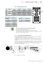
7.6.3 Connection to the swivel angle sensor
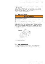
The swivel angle of the pump is acquired by swivel angle sensor VT-SWA...G15,
which is directly connected to pilot valve VT-DFPD in the factory. The sensor is
supplied by pilot valve VT-DFPD.
Pinout of central
connector
Pin
Signal
Description
Signal
dire-
ction
Signal type
Pin assignment in cable
set (accessories)
1
+ UB
Power supply
IN
24 VDC
1
Supply cable
3 x 1.0 mm²
2
0 V = L0
Reference potential for voltage supply
‒
‒
2
PE
Ground
Ground connection for the electronics
‒
‒
Green/
yellow
3
DO
Switching output 24 V, max. 1.5 A
Factory setting: Error signal
OUT
Logical 24 V
White
Supply cable
10 x 0.14
mm
2
shielded
(shield has to
be connected
to the control
on one side)
4
M0
Reference potential for analog signals
‒
‒
Yellow
5
AI2
Analog input 2
(or digital input, to be configured using
software)
IN
Analog ±10 V
(digital 24 V)
Green
6
AO2
Analog output 2
Factory setting: Actual swivel angle value
normalized
OUT
Analog ±10 V or
0…20 mA
1)
Violet
7
AI1
Analog input 1
(or digital input, to be configured using
software)
IN
Analog ±10 V
(digital 24 V)
Pink
8
AO1
Analog output 1
Factory setting: Actual pressure value
normalized
OUT
Analog ±10 V or
0…20 mA
1)
Red
9
DI
Digital input (use freely configurable)
IN
Logical 24 V
Brown
10
Actual
pressure
value H
Actual pressure value input (analog input 8):
Signal level dependent on parameter setting.
Factory setting depending on option 9 in the
ordering code: 0 … 10 V (V) or disabled (F)
IN
Analog 0 ...
10 V (freely
configurable)
Black
11
Actual
pressure
value L
‒
Analog
Blue
n.c.
Gray

