54/96
SYDFED-2X, SYDFED-3X, SYHDFED-1X
| Installation
Bosch Rexroth AG, Edition 11.2021, RE 30017-B
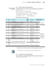
7.6.4 X2M1 and X2M2: Analog, configurable sensor interface (coding A),
M12, 5-pin, socket
Table 12: Pinout of X2M1 and X2M2
Pin
Pin assignment
1
+ 24 V voltage output (sensor supply)
1)
2
Sensor signal input current (4 … 20 mA)
2)
3
GND
4
Sensor signal input voltage (0 … 10 V)
2)
5
Negative differential amplifier input for pin 4
(optional)
1) Maximum load-carrying capacity 50 mA, voltage output identical to the voltage supply
applied to input XH4.
2) Only one signal input can be configured per interface
7.6.5 X7E1 and X7E2: Plug-in connector pinout for Ethernet interface (coding
D), M12, 4-pin, socket
Table 13: Pinout of X7E1 and X7E2:
Pin
Pin assignment
1
TxD +
2
RxD +
3
TxD -
4
RxD -
5
not assigned
Use a shielded data cable as bus cable. The shield should be connected to the
connector housing.


