RE 30017-B, Edition 11.2021, Bosch Rexroth AG
Installation |
SYDFED-2X, SYDFED-3X, SYHDFED-1X
55/96
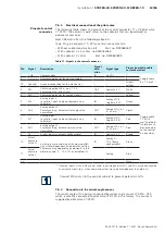
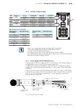
7.6.6 LED status indicator lamps
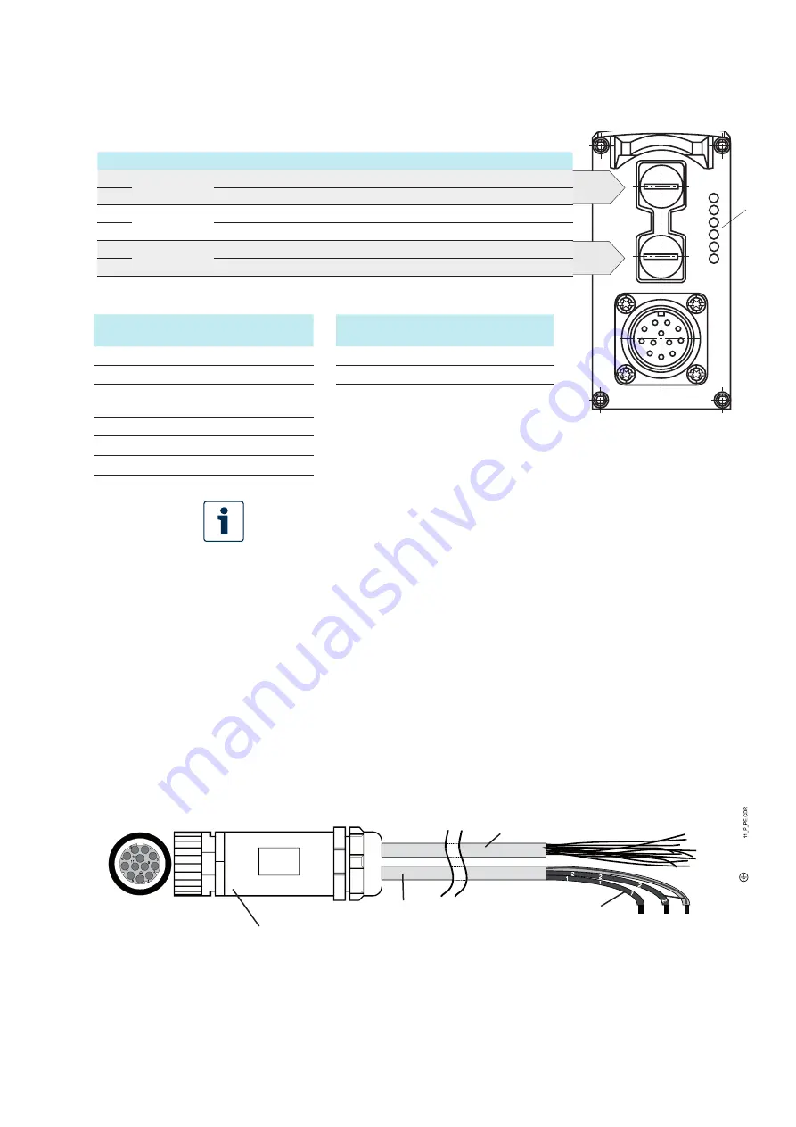
LEDs 1, 2, 5, and 6 refer to the interfaces “X7E1“ and "X7E2“
- Link: Cable pugged, connection is established (solid on)
- Activity: Data sent/received (blinking)
The module status LEDs 3 and 4 refer to the electronics module
For a detailed description of the diagnostic LEDs, please refer to the functional
description of Rexroth HydraulicDrive.
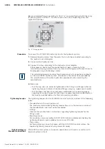
7.6.7 Power supply of the VT-DFPD pilot valve
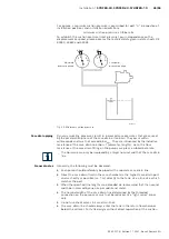
The pilot valve VT-DFPD is supplied with 24 V DC voltage. If this voltage supply is
not provided on the part of the system, power supply unit
VT-NE30-2X/ according to RE 29929 can be used. The 24 V supply of the power
supply unit is to be connected to connections 1 (+24 V) and 2 (L0) of the mating
connector.
In the case of the connection cable optionally available, this refers to the 2 black
wires of the 3-pin cables with a cross-section of 1 mm². Connect the wire marked
with “1“ to +24 V and the wire marked with “2” to L0 (ground). Connect the
yellow/green wire to ground.
Fig. 22: Connection of power supply
Table 14: Indication of status LED
Module status
LED (LED 4)
Indication status
Network status
LED
Indication status
Off
No voltage supply
Off
No voltage supply
Green/red blinking
Self-test
Green
Operation
Flashing green
Drive ready for
operation
Green
in control
Flashing red
Warning
RED
Error
LED
Interface
Sercos
EtherNet/IP
EtherCAT
PROFINET
1
X7E1
Activity
Activity
not used
Activity
2
Link
Link
Link/activity
Link
3
Electronics
module
S
Network status Network status Network status
4
Module status
Module status
Module status
Module status
5
X7E2
Activity
Activity
not used
Activity
6
Link
Link
Link/activity
Link
Socket on valve
VT-DFPD
Connection cable for
voltage supply
Connection cable for signals
Green/yellow
=
Black (2) =
pin 2
Ground
connection
0 V
+24 V
Black (1) =
pin 1


