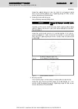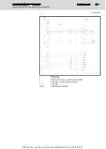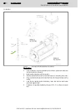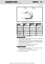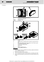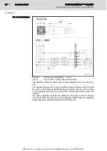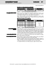
Fig.8-3:
Connecting the power and encoder cables
Designation
Connection
mm²
Stripping length
mm
Tightening torque
Nm
Clamp power U1, V1,
W1
0.5 … 16.0
12
1.5 … 1.8
Clamp
temperature
sensor
0.25 … 2.5
7
0.5 … 0.6
Stud for PE and
shield
M8
-
13.0
Ring terminal for PE
M8
6 … 8
6.0
Ring terminal for
shield power
M8
6 … 8
6.0
Ring terminal for
shield encoder
M3
6 … 8
1.3
Tab.8-3:
Connection screws terminal box
Connect the power cable
●
Insert the ready-made power cable into the terminal box and tighten the
cable gland with the specified torque.
●
Do protective conductor and shield connection and tighten them with the
specified torque. Observe correct design of combined grounding con‐
nector and shield connector according to
fig. 8-2 "Mounting instruction
(electrical connection)" on page 54
.
●
Connect power wires and tighten with the specified torque.
●
Plug the cable ties for temperature and engage.
Connect the encoder cable
●
Insert the ready-made encoder cable into the terminal box and tighten
the cable gland with the specified torque.
●
Do shield connection and tighten with the specified torque.
●
Plug the encoder and engage.
DOK-SYTROX-MPA01******-IT02-EN-P
Rexroth Sytronix SvP 70xx Motor-Pump Unit MPA01
Bosch Rexroth AG
55/123
Connection
LSA Control S.L. www.lsa-control.com comercial@lsa-control.com (+34) 960 62 43 01


