570
Bosch Rexroth AG
| Tightening Technology
3 608 878 300
System 350
| 3 608 878 300/2019-03
IMenip
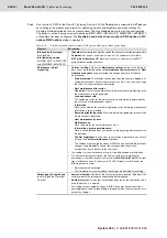
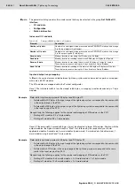
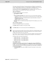
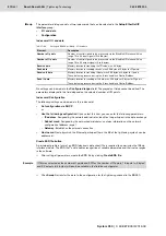
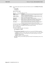
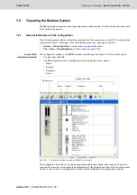
This parameter dialog consists of two index cards that can be selected in the
Setup EtherNet/IP
interface
group:
•
I/O and data
•
Configuration
Index card: I/O and data
No settings can be made in the
Configured ranges
field: The grayed out fields cannot be edited. The
parameters displayed in this field depend on the selected number of I/O points.
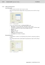
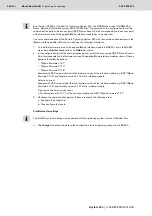
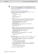
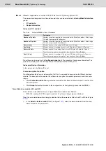
Index card: Configuration
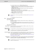
The following settings can be made in this index card:
•
Get configuration via DHCP
or
•
Use the following configuration:
If you select this item, you can enter the following parameters:
–
IP address
: Assigned by the network administrator; identifies the participant in the data exchange
–
Subnet mask
: Assigned by the network administrator; contains information on the network
configuration (address range)
–
Gateway
: Establishes the external connection
•
Host name:
Name by which the Ethernet participant (here the KE of the tightening system) can be
addressed.
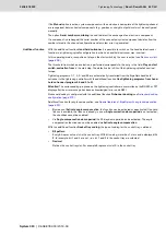
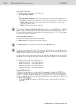
Create ESD file button
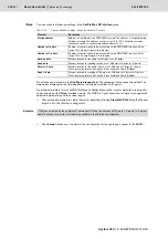
A participant profile in form of an EDS (electronic data sheet) file is required to commission the IMenip
interface module. The EDS file (
*.
eds
) enables recognition of variable parameters and their value ranges
in the software.
After setting all parameters, create the EDS file by clicking
Create EDS file
.
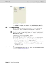
Click
Accept
to transfer the data to the configuration for the tightening channel in the BS350.
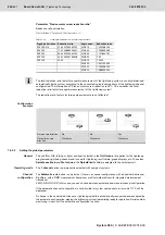
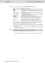
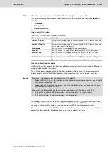
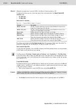
Table 7–20:
Settings in BS350 for IMenip - I/O and data
Element
Description
Number of I points
Number of control signals to be processed via the EtherNet/IP interface: Value
range 16 to 64 input signals (2 to 8 bytes)
Number of O points
Number of control signals to be processed via the EtherNet/IP interface: Value
range 16 to 64 output signals (2 to 8 bytes)
Receive data
Memory location for receiving the ID code, max. 64 bytes
Send data
Memory location for sending results, max. 254 bytes at 2 bytes for O points
Receive IL data
Memory location for receiving IL data, max. 254 bytes at 2 bytes for I points
These data are processed using the IL function block ControlFieldbus.
Send IL data
Memory location for sending of IL data, max. 254 bytes at 2 bytes for O points
These data are processed using the IL function block ControlFieldbus.
Example
If 16I was selected as the number of I points and 32O as the number of O points, 16 inputs (= 2 bytes)
and 32 outputs (= 4 bytes) will also be available in the field bus configurator.
Summary of Contents for Rexroth Tightening System 350
Page 4: ...4 641 Bosch Rexroth AG Schraubtechnik System 350 3 608 878 300 2019 03 ...
Page 120: ...120 641 Bosch Rexroth AG Tightening Technology 3 608 878 300 System 350 3 608 878 300 2019 03 ...
Page 194: ...194 641 Bosch Rexroth AG Tightening Technology 3 608 878 300 System 350 3 608 878 300 2019 03 ...
Page 638: ...638 641 Bosch Rexroth AG Tightening Technology 3 608 878 300 System 350 3 608 878 300 2019 03 ...

