background image

3 608 878 300

Tightening Technology |  

Bosch Rexroth AG

65

/641

System 350

  |  3 608 878 300/2019-03

4.1.5

Tightening processes

A bolted connection should be designed in a way that the minimum mounting clamp force reached 
guarantees the function of the bolted connection, but the maximum mounting clamp force does not 
destroy the bolted connection or the bolt.

The following tightening processes are available for this:

Angle of turn-controlled tightening process

Torque-controlled tightening process

Yield-point controlled tightening process

Special tightening processes, e. g. loosening/retightening sequences. 

4.2

Tightening system design

This chapter describes the criteria for designing a tightening system.

4.2.1

Tightening spindle

Assembly note

If a tightening spindle is installed horizontally, an additional support of the tightening spindle (e. g. near 
the gearbox) is recommended.

4.2.1.1

Size

The torque necessary for the bolted connection determines the size of the tightening spindle. 

Example

Requirements for the tightening spindle:

– 5 tightening spindles

– Torque:

Pre-tightening with 200 Nm, synchronous final tightening of all tightening positions to 180

°

 (approx. 400 Nm)

– Center-to-center distance: 200 mm

– Tightening depth: approx. 50 mm

– Tool mount: 3/4'' square

– Measurement of torque and angle of turn as close as possible to the bolt (no gearbox between measurement 

transducer and bolt)

CAUTION

Risk of injury

If tightening processes with higher torques are implemented with a hand-held tightening spindle, the 
forces may result in injuries, particularly at the joints.

Please use a torque support.

Example

In the product catalog, the example represents a tightening spindle size 5: Working range 50-500 Nm

– Straight output drive GK3C281 (short output drive with sufficient range of spring)

– Measurement transducer 5DMC530 (if necessary, also with redundant measurement transducer)

– Planetary gearbox 5GE68

– EC  motor  EC305

Summary of Contents for Rexroth Tightening System 350

Page 1: ...Rexroth Tightening System 350 Version AL EN Project planning aid 3 608 878 300 03 2019 Replace this image space with your product image ...

Page 2: ...n Our products are subject to a natural process of wear and aging This document as well as the data specifications and other information set forth in it are the exclusive property of Bosch Rexroth AG It may not be reproduced or given to third parties without its consent The title page shows an exemplary configuration The supplied product may therefore vary from the illustration Translation of the ...

Page 3: ...us Comments 3 608 878 300_AA EN 04 2009 Version for Rexroth Tightening System 350 and Operating System BS350 V2 100 3 608 878 300_AB EN 04 2010 Version for Rexroth Tightening System 350 and Operating System BS350 V2 100 and V2 200 3 608 878 300_AC EN 06 2011 Version for Rexroth Tightening System 350 and Operating System BS350 V2 100 and V2 200 3 608 878 300_AD EN 12 2011 Version for Rexroth Tighte...

Page 4: ...4 641 Bosch Rexroth AG Schraubtechnik System 350 3 608 878 300 2019 03 ...

Page 5: ...3 3 1 Compact system 34 3 3 2 Modular system 37 3 4 Description of the Tightening System 350 39 3 4 1 CS351 compact system 39 3 4 2 Modular system 43 3 4 3 Tightening spindles 46 3 4 4 ErgoSpin hand held nutrunner 47 3 4 5 Cables 54 3 4 6 Software 54 3 5 Integration in an entire system 55 3 5 1 Compact system 55 3 5 2 Modular system 56 3 5 3 Communication between the tightening system and the BS35...

Page 6: ...nce 175 5 6 SE timing diagrams 178 5 6 1 Switching on the tightening controller 178 5 6 2 Normal tightening process with program change and without results reset 179 5 6 3 Cancelation of a tightening process by removing the start signal 179 5 6 4 Recognition of play at start switch 180 5 6 5 Controlling the ErgoSpin by an external controller 180 5 6 6 Cancelation of a tightening process by system ...

Page 7: ... BS350 operating system 435 6 8 2 Parameter of results output 436 6 8 3 Example Calculation of the data volume for results files 443 6 9 VW XML 2 x Protocol 445 6 9 1 Settings in the BS350 operating system 446 6 9 2 Configuration of the OK NOK counter for VW XML 448 6 9 3 PLC signals 449 6 9 4 Tightening status code SSC and tightening status messages 451 6 9 5 Messages 452 6 9 6 Process data 453 6...

Page 8: ...3 7 6 4 Configuring the tightening channels 604 7 6 5 Defining the tightening program 606 7 6 6 Defining a tightening application 606 7 6 7 SE PLC assignment table 608 7 6 8 KE PLC assignment table 609 7 6 9 Setting the KE time 610 7 6 10 Sequence test 610 7 7 Saved automatic channel configuration 611 7 7 1 Compact system 612 7 7 2 Modular system 613 7 7 3 Configuring the tightening channel 617 7 ...

Page 9: ...tion This chapter contains general information on the present documentation Overview of this documentation page 10 Validity of the documentation page 10 Additional documentation page 11 Representation of information page 13 ...

Page 10: ...ferences to the Nexo cordless Wi Fi nutrunner Chapter Title Contents 1 About this documentation Validity of this document abbreviations designations used glossary 2 Safety instructions Safety precautions on how to avoid hazardous situations when using Rexroth tightening systems Information on the intended use of Rexroth tightening systems 3 Introduction to the Tightening System 350 This chapter de...

Page 11: ...on safety instructions precede an instruction when there is the danger of personal injury or damage to equipment The hazard avoidance measures described must be observed Safety instructions are structured as follows Safety sign warning triangle draws attention to the danger Signal word identifies the degree of the risk hazard class Type of danger identifies the type or source of the danger Consequ...

Page 12: ...ol Explanation Prerequisite Ensure that the stipulated prerequisite is met before proceeding to the next step Step This symbol indicates an individual step 1 2 3 Sequence of steps Take the steps specified while following the order specified Result This symbol indicates the result of a step Example Examples are in a gray field and illustrate the previously stated information A tip provides addition...

Page 13: ...ll be overwritten with the latest data if more storage space is required Tightening process The tightening process describes the entire tightening procedure including the various individually parameterized tightening program steps such as finding driving in tightening etc until the target function is reached torque angle etc Tightening application Within a tightening application also called applic...

Page 14: ...he angle of turn for a target or monitoring function The monitoring function of the angle is started as soon as the measured torque for the bolt reaches the value for the torque threshold for the first time Afterwards the torque threshold has no more influence on the tightening process except for angle correction SE Control unit Each Compact System consists of a single control unit Chord angle The...

Page 15: ...en the measured angle and the angle on the bolt as a result of the torsion of the output drive due to the torque This deviation can be avoided with an angle correction at the end of the tightening process never during tightening The angle value measured at the end of tightening after falling below the torque threshold is then used as the target or last monitoring parameter the torsion of the outpu...

Page 16: ...ule IMpdp PROFIBUSDP interface module IMpnio PROFINETIO interface module IMpnio2 PROFINETIO interface module KE350 System 350 communication unit without DVI interface KE350G IL System 350 communication unit with DVI interface and integrated logic LT35x Size dependent servo amplifiers for System 350 stationary tightening technology LTS350D Servo amplifier for tightening spindle LTU350 1 Servo ampli...

Page 17: ...ontains important information that is necessary for the safe use of the Rexroth tightening system About this chapter page 18 Intended use page 21 Improper use page 22 Personnel qualifications page 23 General safety instructions page 24 Product and technology dependent safety instructions for Rexroth tightening system 350 page 25 ...

Page 18: ...mponents please contact your Bosch Rexroth sales representative Request that documents be immediately sent to the person responsible for safe operation of the Rexroth tightening system If the Rexroth tightening system and components are sold lent or otherwise passed on within the European Union EU these safety instructions must also be included in the language of one country of the European Union ...

Page 19: ...ly use accessories and spare parts that are approved by the manufacturer Observe the safety regulations of the country in which the Rexroth tightening system and components are used Rexroth tightening system components are designed for installation in machines used in industrial applications Always observe the ambient conditions specified in the product documentation of the respective component Le...

Page 20: ...re authorized by the operator to access the system s direct operating area This is also valid when the system is standing still In case of an emergency fault or any other anomalies switch the system off and protect it against being switched on again Only operate the control and power electronics for Rexroth tightening technology in a grounded network Operation in non grounded networks IT network i...

Page 21: ...o ensure intended use Anyone who deals with our products in any manner must read and understand the appropriate safety instructions and information on intended use If dealing with hardware products they must be kept in their original state i e no modifications may be made to them Software products may not be decompiled and the source code may not be changed Damaged or faulty products may not be in...

Page 22: ...ave not been explicitly approved by Bosch Rexroth Always observe the safety instructions in the respective documentation See the associated documentation for information on the application areas for the respective components As the manufacturer Bosch Rexroth does not grant any warranty assume any liability or provide compensation for damages caused by improper programming or configuration of the t...

Page 23: ...g system and components as well as all warnings and precautionary measures in accordance with this documentation and the documentation of the respective component Personnel must also be trained instructed or authorized to switch electrical circuits and devices on and off in accordance with the accepted rules of safety and current technology ground them and mark them according to the job requiremen...

Page 24: ...ious injury due to electric shock DANGER Dangerous movements Danger to life risk of serious injury or damage to equipment due to unintended motor movements WARNING High voltage due to improper connection Danger to life or risk of serious injury due to electric shock WARNING Health risk for persons with pacemakers metal implants and hearing aids in the immediate vicinity of electrical equipment CAU...

Page 25: ...supply wait 10 seconds for the system to discharge before opening the housing or starting repair maintenance work For electrical drive and filter components After switching off take the specified discharging time for the respective components into account before accessing the devices To eliminate the risk of contact measure the voltage of the condensers before starting work Do not touch the electr...

Page 26: ...ll electric devices and motors to the protective conductor at the grounding points or ground them Even prior to quick tests Before commissioning even for testing purposes always connect the protective conductor or connect with ground wire Otherwise high voltages can occur on the housing that may cause an electric shock Ensure that PE connections are not affected by mechanical chemical or electroch...

Page 27: ... switched on or after operating for an indefinite time WARNING Dangerous voltage inside device Danger to life risk of injury due to electric shock Switch the device off Disconnect the device from the mains supply Compact System CS Before opening the device or starting maintenance work wait at least 90 seconds for the device to discharge Card rack BT and system box SB Before opening the device or s...

Page 28: ... eliminate malfunctions in the connected drives However in view of personal safety especially that involving risk of injury and or damage to equipment this alone is not sufficient Until the installed monitoring devices become fully effective faulty drive movements whose magnitude depends on the controller type and the operating condition must be anticipated ...

Page 29: ...heck the function of the emergency OFF system before commissioning If the emergency OFF switch malfunctions do not operate the device Protection against unintended start up by means of an emergency OFF circuit Safely bring the drives to a standstill before accessing or entering the danger zone Additionally secure vertical axes from falling or dropping after the motor is switched off by Mechanical ...

Page 30: ... pacemakers need to enter these types of areas a physician must first be consulted The interference resistance of current or future pacemaker versions varies greatly For this reason no generally applicable rules exist Persons with metal implants metal shrapnel in the body or hearing aids must consult a physician before entering these types of areas as adverse health effects must be expected in the...

Page 31: ...y shoes protective gloves Do not stand under suspended loads Any fluids that have leaked onto the floor must be wiped up immediately to prevent slip hazards Lay cables and lines in accordance with the permissible bending radiuses so that they cannot be damaged and no one can trip over them CAUTION Risk of injury due to improper handling The improper handling of batteries may lead to chemical burns...

Page 32: ...ury due to improper handling of pressurized lines The improper handling of pressurized lines may cause explosions that can again lead to injuries Never attempt to disconnect open or cut pressurized lines risk of explosion Observe the operating instructions from the respective manufacturer Discharge the pressure and medium from lines before disassembly Use suitable protective equipment for example ...

Page 33: ...tem 350 It describes the individual components and explains how they are integrated in the entire system The Tightening System 350 page 34 Definitions page 34 System design page 34 Description of the Tightening System 350 page 39 Integration in an entire system page 55 Process Quality Manager PQM page 58 ...

Page 34: ...fety components within the meaning of the machinery directive 2006 42 EC Thus these components are not covered by the standard EN ISO 13849 Safety related control parts The modular tightening spindle is connected to the power electronics by just one connecting cable and is equipped with torque and angle of turn sensors to constantly monitor the tightening Tightening systems with up to 40 tightenin...

Page 35: ...systems operated as slave of a modular system as of version V2 200 of the Rexroth Tightening System 350 see Figure 3 3 Self dependent operation Fig 3 1 Single channel tightening system based on the CS351E G IL compact system with ErgoSpin hand held nutrunner and portable Nexo radio nutrunners Fig 3 2 Single channel tightening system based on the CS351S G IL compact system with tightening spindle a...

Page 36: ...s an additional networking option In this case compact systems can accept the role of the master similar to BT356 and SB356 in figure 3 3 The master CS351 can then communicate with up to three slave CS351 and control them The communication between master CS351 and slave CS351 is effected via the data service Rexroth Open Protocol see Rexroth Open Protocol from page 330 Programming Programming is i...

Page 37: ...with TFT display resolution 640x480 with touch screen CS351S G IL additionally with integrated logic see Project planning documentation of the Rexroth Tightening System 350 CS351S D with LC display and DVI interface to connect an external DVI monitor CS351S D IL additionally with integrated logic see Project planning documentation of the Rexroth Tightening System 350 CS351S D NK for networking as ...

Page 38: ...such a configuration the compact system replaces the control unit Communication is implemented via the following network couplers NK350S in the modular system NK350 in the compact systems 1 15 The BS350 operating system has a menu assisted user interface which makes it easy to configure and program the tightening channels via a laptop or PC Card rack fields can be quickly and simply integrated in ...

Page 39: ...r one tightening channel It can withstand ambient temperatures of up to 40 C without an air conditioning unit and thus helps reduce operating costs It is protected according to IP54 The following types of compact systems are available Compact systems operated self dependently see Figure 3 5 Compact systems operated as slave of a modular system as of BS350 operating system version V2 200 Compact sy...

Page 40: ...witch X1N Power supply connection for 120 V 230 V1 1 The Compact System CS351 is not designed to be directly connected to the public low voltage power supply but is only intended for use in industrial environments emission classA XDS1 Connection for ErgoSpin hand held nutrunner2 CC ErgoSpin only CS351E G and CS351E D with without IL CS351E G CS351E D NK CC CS351E D 2 Differences between the connec...

Page 41: ...s for the use of standard type B modules serial 24 V CS351E G and CS351S G do not feature slot B2 due to the integrated computer unit Reset Restart reset button X3C1 RS232 interface to CS351 controller X7E1 Ethernet interface to CS351 controller X6C1 Mass storage slot for CF350 CF card XDVI DVI interface to connect an external monitor X3U4 No function USB host interface for connection of an extern...

Page 42: ...to connect a scanner The reason for missing interfaces IL and data services is that these functions are integrated into the KE of the modular system The CS351 D NK compact systems may be operated as single channel or as part of a tightening application Then the compact system is displayed as further channel in the channel selection list of the operating system BS350 Special feature CS351 G with in...

Page 43: ... to 40 tightening channels can be networked using network couplers and network coupler cables A space saving design allows for easy integration in an entire system 3 4 2 2 BT356 card rack field Fig 3 10 BT356 card rack field The card rack fields have been designed for installation in 19 standard systems They can be installed directly on top of each other in an especially space saving manner All co...

Page 44: ... implements the system diagnosis and monitors all individual components of a tightening channel Depending on the control unit the following interfaces are available 3 4 2 5 Servo amplifiers for tightening spindles and ErgoSpin hand held nutrunners The digital servo amplifiers control the EC motor or the ErgoSpin hand held nutrunner The control parameters are digitally transmitted by the control un...

Page 45: ...he KE350G IL It can be freely programmed in accordance with IEC 61131 3 and provides the user with countless automation options for the entire tightening process Depending on the communication unit the following interfaces are available X3U1 X3U2 Two USB host interfaces compatible with specification 2 0 X3U3 USB device interface specification compatible with 2 0 Slot A Slot for the use of type A s...

Page 46: ...nt transducer 3 The measurement transducer is designed as a contact free maintenance free action transducer The measured values e g torque angle of turn and gradient are processed directly in the measurement transducer It is equipped with an integrated cycle counter and can also be used as a redundancy transducer The measurement data is digitally transferred from the measurement transducer to the ...

Page 47: ...runner The operating elements are easily accessible the displayelements are easy to read As an example the SlimLine model variant is described below Fig 3 12 Design of ErgoSpin SlimLine model A Output drive component B Standard machine Output drive a Depending on the model angle head or straight output drives are available The ErgoSpin has a mechanical interface to flange on accessories e g a supp...

Page 48: ...ally exchange data with the power electronics and the controller In addition existing controller signals are evaluated and forwarded accordingly New series of nutrunners The new series of ErgoSpin hand held nutrunners is equipped with a motion detector by default This way the effects of rotary motions of the hand held nutrunner which may occur at tightening tools freely handled by the operator are...

Page 49: ...s 2 laser with low energy diode may result in damages to the eyes retina Do not look directly into the laser beam Do not manipulate the laser source as this may result in an uncontrolled emission of hazardous laser radiation Do not change the specified values as this may result in an uncontrolled emission of hazardous laser radiation Table 3 6 Supported barcode types barcode scanner in the ErgoSpi...

Page 50: ...ecurity Level 0 3 EAN 8 with 2 Supplements 1 Zero Extended Redundancy Security Level 0 3 EAN 8 with 5 Supplements 1 Zero Extended Redundancy Security Level 0 3 EAN 13 1 Redundancy Security Level 0 3 EAN 13 with 2 Supplements 1 Redundancy Security Level 0 3 EAN 13 with 5 Supplements 1 Redundancy Security Level 0 3 Bookland EAN 1 Supplementals Security Level 0 3 UCC Coupon Extended Code 1 Redundancy...

Page 51: ...it verification Check Digit Interleaved 2 of 5 L12 L1 L23 L1 L24 any5 Redundancy Security Level 0 3 Digit verification Transmit check digits Discrete 2 of 5 L12 L1 L23 L1 L24 any5 Redundancy Security Level 0 3 Chinese 2 of 5 1 Redundancy Security Level 0 3 Codebar L12 L1 L23 L1 L24 any5 Redundancy Security Level 0 3 CLSI Editing NOTIS Editing MSI L12 L1 L23 L1 L24 any5 Redundancy Security Level 0 ...

Page 52: ...s operated at There is no check for ID codes used multiply The controller acts as in the versions prior to V2 100 if the barcode scanner is not activated or the barcode scanner is activated but no valid barcode has been detected Optional additional module second start switch All models of the ErgoSpin hand held nutrunner except for the ESM pistol grip nutrunner can be modified with a second start ...

Page 53: ... Starting the hand held nutrunner To start the hand held nutrunner both start switches have to be pressed simultaneously within 0 5 seconds Before restarting the hand held nutrunner both start switches have to be released If fully assembled it complies with all requirements for 2 hand operation according to type III A EN 574 ISO 13851 1 ...

Page 54: ...n cable Measurement transducers are connected via measurement transducer cables 3 4 5 2 Cables for the ErgoSpin hand held nutrunner The ErgoSpin is connected to the CS351 compact system or LTU350 1 or LTE350D servo amplifier via a connection cable 3 4 5 3 Network coupler cables The network coupler cables connect card rack fields and system boxes 3 4 5 4 USB cable The PC with the BS350 operating sy...

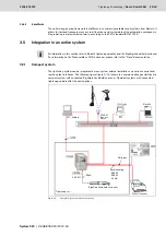
Page 55: ...oss system external installations via various control and results output interfaces The following figure figure 3 16 shows the communication possibilities of a compact system with connected ErgoSpin hand held nutrunner Compact systems with connected tightening spindle offer the same options Fig 3 16 Compact System communication options All information in this section refer to Rexroth tightening sp...

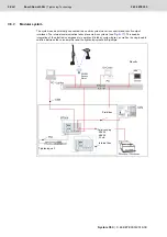
Page 56: ...l and results output interfaces The internal communication takes place via bus systems see Fig 3 17 This enables integration of the electronic components in card rack fields or system boxes as well as the single cable solution between the servo amplifier and the tightening spindle or ErgoSpin Results Field bus Internal bus Tightening cell Serial coupling RS232 RS422 20 mA WLAN Access Point ...

Page 57: ...d the BS350 operating system can take place via USB or Ethernet see preceding figures The BS350 is used to program tightening jobs and to visualize and analyze measurement values For an Ethernet connection the PC must be equipped with a network card For the connection via USB a corresponding supplied driver must be installed on the PC Field bus Internal bus Tightening cell TCP IP Printer scanner S...

Page 58: ...rfaces 3 4 or 5 see Figs 3 16 and 3 17 The ID code is contained in the various data output formats 3 6 Process Quality Manager PQM Process Quality Manager PQM is a software solution of Bosch Rexroth It is designed to recognize and avoid non conformities and errors in the production process as soon as possible PQM offers safe and reliable monitoring and documentation of production processes PQM com...

Page 59: ...ightening System 350 For further information refer to www boschrexroth com tightening Design of a bolted connection page 60 Tightening system design page 65 Integration of the tightening system in an installation page 89 Compatibility with foreign substances page 112 Planning guidelines page 112 Planning assistance page 112 ...

Page 60: ...ning forces exerted the parts to be tightened are pressed together compressed by fPM If operating forces act on the bolted connection the operating force FSA superimposes the mounting clamp force FM The bolt is additionally stretched by fSA while the compression on the material fPM is reduced by the amount fPA The deformed parts are relieved by the axial force fPA but the residual clamp force FKR ...

Page 61: ...e following conditions Machining quality of the parts to be tightened Coarseness tolerances of bolt and nut Material pairs of the parts and bolts to be tightened Surface coating of bolts and components Thread form and pitch The friction consists of a combination of the thread friction and the underhead friction The actual friction itself does not make a calculation of the mounting clamp force from...

Page 62: ...nt The mounting clamp force of a bolted connection is influenced by numerous factors The spread of the friction actually occurring under the bolt head and at the thread only an assumed typical value can be used for calculation Differences depending on the selected tightening process e g fast or slow tightening of the bolt torque controlled angle controlled process yield point tightening Precision ...

Page 63: ... 1 40 1 43 8 50 3 55 8 12 9 33 6 32 8 32 0 31 1 30 2 28 4 26 6 31 8 37 2 42 2 46 9 51 2 58 9 65 3 M10 8 8 31 0 30 3 29 6 28 8 27 9 26 3 24 7 36 43 48 54 59 68 75 10 9 45 6 44 5 43 4 42 2 41 0 38 6 36 2 53 63 71 79 87 100 110 12 9 53 3 52 1 50 8 49 4 48 0 45 2 42 4 62 73 83 93 101 116 129 M12 8 8 45 2 44 1 43 0 41 9 40 7 38 3 35 9 63 73 84 93 102 117 130 10 9 66 3 64 8 63 2 61 5 59 8 56 3 52 8 92 1...

Page 64: ...tia Only then the tightening process can be classified as safe Tightening case determination according to ISO 5393 The definition of a hard or soft tightening case is set out in ISO 5393 as follows Hard tightening case Soft tightening case Increase in torque from 10 to 100 of the target torque within an angle of turn of 27 or from 0 to 100 within 30 Soft tightening case Soft tightening case Increa...

Page 65: ...the gearbox is recommended 4 2 1 1 Size The torque necessary for the bolted connection determines the size of the tightening spindle Example Requirements for the tightening spindle 5 tightening spindles Torque Pre tightening with 200 Nm synchronous final tightening of all tightening positions to 180 approx 400 Nm Center to center distance 200 mm Tightening depth approx 50 mm Tool mount 3 4 square ...

Page 66: ...cle With any adapter an additional measurement transducer can be integrated between VMC and planetary gearbox for extra system security This measurement transducer can also be used as a part of an emergency strategy if one of the two transducers fails This increases the availability of the tightening system even more The redundant measurement transducer is connected via the 3AR or 4AVR redundant a...

Page 67: ...utput drives e g accessible via the Internet at www boschrexroth com tightening are decisive The following table shows the available output drives and the resulting minimum circle diameters for all sizes Table 4 3 Angle head Code 2W011 3W027 3W050 3W090 4W130 4W220 Order number 0 608 810 041 0 608 810 042 0 608 810 043 0 608 810 044 0 608 810 045 0 608 810 046 Max permissible axial force F see tab...

Page 68: ...ck change chuck The quick change chuck allows for exchanging a tool socket quickly Offset output drive with integrated measurement transducer 2 3 3VMC 31 36 44 53 62 4 4VMC150 44 51 63 75 88 4VMC210 48 56 68 82 96 4VMC360 57 66 81 97 114 5 Angle head 2 2W011 26 30 36 44 52 3 3W027 29 34 41 50 58 3W050 35 40 50 60 70 3W090 45 52 64 78 90 4 4W130 47 55 67 80 94 4W220 62 72 88 106 124 5 Angle head wi...

Page 69: ...machine and an angle head The angle head is mechanically coded and can only be operated on the appropriate standard machine This results in a high level of process reliability The efficiency of the angle head is stored in the nutrunner at the factory before delivery Special angle heads cannot be mounted The parameters of the output drive efficiency transmission ratio are stored in the ErgoSpin and...

Page 70: ...machine It is equipped with a configurable tightening position illumination The output drive interface in SD models is square in QD models it is a quick change chuck for simple assembly and disassembly of the tool The HT models are equipped with a square plus Hirth toothing This allows to flange a planetary gearbox thus enabling high tightening torques 4 2 3 Connection cables Thanks to the single ...

Page 71: ...different cable types are illustrated with order numbers in the current product catalog NOTICE Malfunction damage to system Functional safety and system safety jeopardized Only use accessories add on units and cables that have been approved for use in Rexroth tightening systems On assembly the connection cables are to be tightened by hand A suitable tool may also be used for assembly pipe wrench w...

Page 72: ...onnection cable for tightening spindles at the compact system plugged in or in one piece must not exceed 50 m Note The length of the connection cable for certain components may be limited You must therefore observe the length specification if stickers with limitations are attached to the components Measurement transducer cables with different lengths are available to connect motor and measurement ...

Page 73: ... ErgoSpin connection cable angle straight E ErgoSpin connection cable angle straight with freely rotatable angle plug F ErgoSpin connection cable angle angle with freely rotatable angle plug NOTICE Damage Excessive tightening of the freely rotating angle plug may lead to damage Please observe the angle of turn of the freely rotating angle plug The angle of turn has an impact on the service life of...

Page 74: ...r certain components may be limited You must therefore observe the length specification if stickers with limitations are attached to the components Observe the minimum bending radius of connection cables Once 3 x cable Repeated 7 5 x cable Optimum 10 x cable Connection cables are available with straight plugs and angle plugs The cable outlet on the angle plug is adjustable to run the cable in the ...

Page 75: ...kg 7 kg Due to the data transmission times Rexroth recommends connecting a maximum of 8 tightening channels in single channel operation within a tightening system Example Two card racks system boxes total of 6 slots with KE are needed for the 5tightening channels in the example on page 65 as the power consumption of the 5tightening channels 225 A exceeds the permissible power consumption of 140 A ...

Page 76: ...htening process Combination of multiple card rack fields and system boxes Up to 40 tightening channels distributed to up to 16 card rack fields system boxes can be networked using a NK350 or NK350S network coupler and the NKL network coupler cable In this the communication unit coordinates the individual control units and organizes the interfaces to external systems e g PLC or central computer A s...

Page 77: ...4 7 In this the communication unit coordinates the individual compact systems and organizes the interfaces to external systems e g PLC or central computer A unique rack address adjustable at the tack coupler has to be for each compact system The slot for each compact system always is 1 which results in the following channel numbers at the most 0 1 1 1 2 1 15 1 Networking the compact systems as sla...

Page 78: ...2 5 Connected load 4 2 5 1 Compact system The CS351 compact system is designed as follows Nominal voltage 120 230V Nominal current 10 5 2A Nominal power 1200 VA Peak power 4800 V 4 2 5 2 Modular system The connected load needed for a card rack field or system box depends on the number and size of the tightening channels to be operated Calculations should be based on fully equipped card rack fields...

Page 79: ...higher we recommend a 3 phase connection via a transformer 3 x 400 V 10 50 60 Hz 380 V to 500 V 2 2 Adjustable via X1N4 interface on SB356 NOTICE Overvoltage Destruction of devices A transformer is always necessary if a BT356 is connected to an industrial network see also figure 4 29 All three mains phases must be connected with a mains balanced to earth Table 4 11 Single phase connected load depe...

Page 80: ...ains phase is grounded is not permissible The connection incl PE must be designed as a 3 phase connection 4 x 2 5 mm2 To avoid short circuits and ground leakage a 3 phase 16 A fuse must be provided In addition a PE wire with a minimum cross section of 10 mm2 Cu must be connected at the X1N3 1 X1N3 2 interface underneath the system box see Fig 4 8 Fig 4 8 PE conductor connection to X1N3 1 X1N3 2 Th...

Page 81: ...al card rack fields to the mains supply Connecting two BT356 to the Mains supply Fig 4 9 Connection example for 2 BT356 card rack fields with a shared isolating transformer Connecting two SB356 to the Mains supply Fig 4 10 Connection example for 2 SB356 system boxes to a three phase voltage supply BT356 BT356 SB356 SB356 ...

Page 82: ... power demand of 6 W at 55 min 1 For pre tightening For final tightening Approximately the same power is calculated for the power loss in the servo amplifier Table 4 14 Power consumption of the installed components Module Static power consumption Tightening spindle LT35x or ErgoSpin LTU350 1 19W CS351E D IL 23W 1 1 Power loss in ready mode CS351E G IL 26W 1 23W 2 2 23 W with activated screensaver ...

Page 83: ...rmula abbreviations for the calculation of total power loss Formula abbreviations T Cycle time PG Base load according to the equipment t1 Tightening cycle time t2 Pre tightening duration t3 Final tightening duration P1 Tightening power loss P2 Pre tightening power loss P3 Final tightening power loss n Number of channels Pv Power loss Tightening Pre tightening Final tightening Base load t1 10 55min...

Page 84: ...ightening process 4 2 7 2 Heat dissipation from tightening spindle and servo amplifier Heat dissipation is influenced by the difference in temperature in the module motor servo amplifier and the ambient temperature The amount of heat that has to be dissipated depends on the speed and torque of the motor and also the cycle time spindle run time in percent per cycle The following diagrams show the c...

Page 85: ...s right for size 4 spindles with i 1 on the output drive Max heat dissipation capacity of the servo amplifier installed in the BT356 Max heat dissipation capacity of the motor Hard tightening case Soft tightening case Max heat dissipation capacity of the servo amplifier installed in the BT356 Max heat dissipation capacity of the motor Hard tightening case Soft tightening case 2 0 50 T Nm 40 30 20 ...

Page 86: ...loss using the diagrams The displayed diagrams may be used to determine the cycle time and maximum performance For this the axes of the diagrams must be adjusted to correspond to the specifications of the tightening to be dimensioned Max heat dissipation capacity of the servo amplifier installed in the BT356 Max heat dissipation capacity of the motor Hard tightening case Soft tightening case 200 4...

Page 87: ...rdness right with different output drive VUK3D In the left diagram a tightening torque of 400 Nm results in a maximum speed of 22 min 1 With a speed of 20 min 1 the maximum performance is not exceeded In the right diagram a pure tightening torque pre tightening and final tightening is specified with 4 5 sec altogether A tightening torque of 400 Nm and soft tightening case see definition on page 64...

Page 88: ...ge 42 4 2 9 Display Depending on the model the CS351 compact system is equipped with a TFT display CS351E G IL and CS351S G IL or an LC display CS351E D IL CS351S D IL CS351E D NK and CS351S D NK LTU350 1 LTS350D and LTE350D are also equipped with LC displays An external monitor can be connected to the CS351E D IL or CS351S D IL compact system and to the KE350 G IL to display tightening results vi...

Page 89: ...ng System 350 have been designed for use in an industrial production environment The ambient conditions required for trouble free operation are found in the technical data of the respective operating instructions CS351 SB356 BT356 Protection classes The system components comply with the following protection classes Compact system SB356 IP 54 BT356 IP 20 Tightening spindles IP 54 ErgoSpin IP 40 BT3...

Page 90: ...is may damage the control and power electronics Penetration of water into the compact system card rack field or system box must be avoided in any case At higher humidity values 70 constructive measures must be taken to prevent condensation Control cabinets with heaters are a possible solution A control with thermostats and hygrostats is recommended K H 0 m 100 90 80 70 60 50 1000 m 2000 m 3000 m 4...

Page 91: ...depend on the module controller measurement transducer etc and the installation location of the sensors within the module see table 4 20 For diagnosis purposes the BS350 operating system provides an overview of the current system status under System test Tightening cell info Temperature This overview is an aid for evaluating the temperature conditions in the system Using this and the limit tempera...

Page 92: ... They may lead to interferences in the electronic system Connection via the rollers to the steel beam system is not possible as the rollers often consist of plastic Table 4 20 Temperature limits at the temperature sensors Limit temperature Error Error class CS 72 C Error 1010 Temperature warning level Temperature warning level reached 3 75 C Error 1011 Temperature error Permissible temperature exc...

Page 93: ...pact System The CS351 compact system is equipped with an interface XDN1 see figure 4 19 for the motor breaker with two independent circuits for the motor breaker Fig 4 19 Section of CS351 with XDN1 interface Boundary conditions The maximum cable length for the motor breaker circuit is 30 m Always design the motor breaker circuits separately and with potential free contacts Do not confuse the motor...

Page 94: ...nner tightening spindle will be decelerated by the servo amplifier and the internal contactor in the compact system will be opened This tightening job abort leads to an error message in the controller The system can restart after switch S1 has been closed Cut out via the end step In addition the motor breaker can be switched via the end step or together with the cut out via the motor contactors do...

Page 95: ... case of operation this reduces the danger to the operating personnel XDN2 To achieve a central stop of the motor of all servo amplifiers LTU350 1 LT35x TS350D LTE350D the XDN2 user interface see Fig 4 23 must be connected to pin 3 and pin 4 of the power supply module VM350 X1S2 The X1S2 interface see Fig 4 23 enables the external 24 V power supply This ensures the power supply e g to interfaces a...

Page 96: ...er side emergency stop concept An additional external 24V power pack can be connected via the X1S2 interface If the mains power supply is switched off the same supplies the electronics in the Tightening System 350 external field buses such as e g PROFIBUS remain ready for operation Reset LTU350 1 Reset LTU350 1 Reset EXIT INT XDN2 X1S1 VM350 XDN2 VEE NH 1 mm2 X1S2 NH Use emergency OFF switch direc...

Page 97: ...gency OFF is triggered mains supply interrupted no CW CCW should be set as this can lead to system errors The maximum line length between power pack and VM350 must not exceed 5 m Triggering the emergency OFF mains switching is subject to the same time intervals as switching on the mains After the return of the mains power supply wait approx 10 s before setting CW CCW XDN2 24 V 0 V X1S2 Kx Ky 3 3 1...

Page 98: ... to circumstances caused by the system e g special machinery directives the emergency OFF concept must be taken into consideration separately in conjunction with system emergency stop 4 3 2 Design of mains connection The power connections have been designed according to the requirements for category 3 overvoltage Important rules after switching off the device In case of single switching switch the...

Page 99: ...asures System box grounding The design of the system boxes results in a special grounding feature The permanently connected 10 mm2 ground cable on the bottom of the system box is supplemented by grounding through the power supply connection line The same must also be available at all times due to safety reasons Two studs are included on the bottom of the system boxes to simplify the installation o...

Page 100: ...s are generally equipped with an EMC shield to protect against impermissible electromagnetic influences Coupled interferences are conducted to ground via these shields Fig 4 27 Potential difference between ErgoSpin tightening spindle and workpiece NOTICE Leakage currents due to potential differences In practice the CS351 compact system or the installation location of card rack fields or system box...

Page 101: ...ducer The extremely sensitive monitoring electronics for torque detection may in some cases be influenced by this current This influence can only be avoided if no leakage currents flow over the spindle output drive Fig 4 28 Parasitic current The disrupting potential differences cannot be completely avoided as the electric equipment and installation is implemented according to the various customers...

Page 102: ...currents leakage currents occur in the industrial environment due to a potential equalization between nutrunner and workpiece an additional potential equalization via a 10 mm2 gn ge conductor is recommended here A braided copper cable that conducts any resulting stray currents over the compact system to the cable shield is ideal Fig 4 31 Attachment of an additional potential equalization at the CS...

Page 103: ...bution can be determined by applying the standard DIN EN ISO 13849 1 2008 Safety of machinery Safety related parts of control systems The contribution to the risk reduction depends on The severity of the injury to be expected The frequency with which the user is exposed to the danger And the possibility to recognize an imminent danger in due time It is indicated as discrete level specifying the ab...

Page 104: ...lue of 2 1 million switching cycles per year CAUTION Risk of injury due to non compliance with the system specific requirements on an emergency OFF system Risk of short circuit risk of injury The user is obliged to maintain the system specific requirements for an emergency OFF system When designing the emergency OFF circuit the user must observe the rules for the short circuit and cross circuit pr...

Page 105: ...VM350 or XDN3 LTE350D The hand held nutrunner is only stopped if the start switch is released Controller PFHd Hours Performance level1 Comments Modular system350 in connection with LT35x and stationary spindles no channel selective motor stop possible 2 29 10 7 2 d This value applies to the motor stop interface XDN2 upon switching of the emergency OFF circuit by the user no channel selective switc...

Page 106: ...power loss to be dissipated per BT365 the card rack fields may be installed directly above or next to each other or with an intermediate space in between The BT365 card rack field can be bolted to the front side of a 19 installation frame or to the rear on a mounting plate 1According to ISO 13849 1 2006 2 ATTENTION To ensure that the ErgoSpin hand held nutrunner is integrated in the emergency OFF ...

Page 107: ...tate installation of card rack fields in Rittal control cabinets special brackets for 1 2 3 or 4 card rack fields type PS and TS with 500 or 600 mm depth are available The following spoilers are available for optimum air convection in roof climate control units from Rittal SK 3296 800W SK 3290 1400W Climate control In general please take the air convection into account when using climate control u...

Page 108: ...veral tightening positions i e various tightening programs are necessary for reworking and they can be selected by the worker as needed Rework stations typically consist of a hand held nutrunner channel ErgoSpin a hand held stationary tightening channel or a hand held stationary multiple nutrunner Example rework station with CS351 compact system and hand held nutrunner channel The tightening chann...

Page 109: ...le heads with counter bracket Block output drives Feed clamps Suspensions Telescopic balancers Fully automatic tightening stations Accessories for ErgoSpin Holders for right angle nutrunners and straight nutrunners Holders for ESM pistol grip nutrunner Turning suspensions Suspensions for ESM ErgoSpin pistol grip nutrunners Extensions Turning suspensions for ErgoSpin with extension Vertical suspens...

Page 110: ...The value of the input signal depends on the tool removed from the socket tray Here the four inputs 0 0 to 0 3 are used as a 4 bit word Program selection can thus take place by assigning the program selection bits Prog0 to Prog3 in the PLC table For job functionality Haller Erne socket trays of the series MSTKN X XXX XX DB25M and MSTKN X XXX XX DB25M OP are supported 4x socket tray 8x socket tray ...

Page 111: ... 0 3 are used as a 4 bit word The program application can therefore be selected by assignment to the program selection bits Prog0 to Prog3 when connected to a tightening controller or FO x Seq0 to FO x Seq3 when connected to a communication unit in the PLC table 4 3 8 3 Start switch for hand held tightening spindles Fig 4 35 Start switch 3 609 289 800 The start switch is available in several versi...

Page 112: ...g in compliance with standards In this phase realization as well as later utilization are defined Always comply with all applicable regulations safety EMC Decisive standards regulations apply the field of application neutral cabling and current general standards regulations for communication cabling Observe the minimum bending radius of all cables Observe the maximum cable length Only use suitable...

Page 113: ...608 878 300 Tightening Technology Bosch Rexroth AG 113 641 System 350 3 608 878 300 2019 03 4 6 2 Circuit diagrams Fig 4 36 Circuit diagram example for connecting a transformer to a BT356 card rack field ...

Page 114: ...114 641 Bosch Rexroth AG Tightening Technology 3 608 878 300 System 350 3 608 878 300 2019 03 Fig 4 37 Circuit diagram example for connecting several BT356 card rack fields ...

Page 115: ... 300 Tightening Technology Bosch Rexroth AG 115 641 System 350 3 608 878 300 2019 03 Fig 4 38 Circuit diagram example for networking several BT356 card rack fields with NK350 S network couplers and motor breaker ...

Page 116: ...116 641 Bosch Rexroth AG Tightening Technology 3 608 878 300 System 350 3 608 878 300 2019 03 Fig 4 39 Circuit diagram example for connecting tightening spindles to a BT356 card rack field ...

Page 117: ...3 608 878 300 Tightening Technology Bosch Rexroth AG 117 641 System 350 3 608 878 300 2019 03 Fig 4 40 Circuit diagram example for connecting a KE in a BT356 card rack field ...

Page 118: ...118 641 Bosch Rexroth AG Tightening Technology 3 608 878 300 System 350 3 608 878 300 2019 03 Fig 4 41 Circuit diagram example for the start delay at a BT356 card rack field ...

Page 119: ...3 608 878 300 Tightening Technology Bosch Rexroth AG 119 641 System 350 3 608 878 300 2019 03 Fig 4 42 Circuit diagram example for PNOZ ...

Page 120: ...120 641 Bosch Rexroth AG Tightening Technology 3 608 878 300 System 350 3 608 878 300 2019 03 ...

Page 121: ...g System 350 The information provided in this document refers to software versions V2 100 and higher of the BS350 operating system Definitions page 122 Description of all PLC signals page 126 KE communication unit page 156 KE timing diagrams page 163 Tightening controller page 172 SE timing diagrams page 178 ...

Page 122: ...ntroller The tightening program coordinates the tightening process or sequence It is divided into various tightening steps where tightening parameters are set The tightening programs are stored in the tightening controller These programs are controlled by a PLC via PLC signals 5 1 3 Tightening cell FC A tightening cell is designated as the installed hardware for at least one tightening channel and...

Page 123: ...E File New KE PLC assignment table There must be an existing tightening controller configuration before the PLC assignment table can be configured SE CS KE After the PLC assignment table has been opened File New PLC assignment table SE CS or File New PLC assignment table KE a dialog appears asking for the configuration to be used The configuration to be used can either be obtained offline from a c...

Page 124: ...eld The dialog can also be access by double clicking on the signal name By means of the tooltip the name conventions are displayed If the name does not comply with the convention a respective message is displayed The name must have between 2 and 20 characters It must not be identical with an original name of an input or output signal Double entries are not permitted Reset name With this entry the ...

Page 125: ... as dialog KE PLC signal names are saved in the kion file CS SE signal names are saved in the sion file Load name from file This button enables uploading names from a file In the Opendialog select the respective file The PLC signal names are displayed in the PLC assignment table Reset all names This button is only active if a system administrator or user is logged on Display original name If the D...

Page 126: ...15 Communication unit in application operation KE x AppIn 0 15 Application specific signals are used to make special adjustments for customer requirements They are e g suitable for looping through signals a signal can be read by the controller via interface modules and then output to the partner controller using the controller A tightening channel released via the KE with Ch x y ActEn will not be ...

Page 127: ...ning System 350 Input signal used for Compact system AutoBackup Communication unit AutoBackup Setting this signal to High starts the automatic backup if the Auto backup restore function is configured in the operating system see Automatic data backup with backup restore function on page 545 ExampleSE A signal can be read via a 24 V interface of the tightening controller SEAppIn 0 15 and output to t...

Page 128: ... carried out The signal changes to low as soon as the backup has been completed AutoBackupTrgd Auto backup trigger Automatic data backup sequence This signal is available from version V2 600 of the Rexroth Tightening System 350 Input signal used for Compact system AutoBackupTrgd Communication unit AutoBackupTrgd This signal changes to high if the automatic backup has been triggered and could howev...

Page 129: ...ed with this signal As long as the spindle is deselected the respective controller does not respond to the Cw and Ccw nutrunner start signals In this state the controller x y has set the NOK signal to high The Rdy and OK as well as the result signals are low The left LED on the front of the SE flashes green The spindle is only bypassed if an application attempting to access the SE was executed The...

Page 130: ...a interface modules The controller then transfers the signal to the partner controller where it is output Cw Clock wise Starts tightening in clockwise direction Input signal used for Tightening channel Cw Communication unit in single channel operation CH x y Cw Communication unit in application operation FO x Cw A selected tightening program or a selected application is started with the Cw start s...

Page 131: ...ogram is aborted with NOK After an OK NOK evaluation has been made the signal can be set to low without any effect on the analysis The signal must be assigned in the PLC assignment table in order that the AND operation of both signals will be activated Thereafter tightening can only be started when both signals are high CwLock Clock wise lock Disables the starting function Input signal used for Ti...

Page 132: ...quent tightening application Suppression does not apply to outputs within the scope of BS350 and error transmission via HTTP DisRpFtp Disable Report Ftp Suppresses the results output via FTP Input signal used for Tightening channel DisRpFtp Communication unit in application operation KE x DisRpFtp The FTP results output can also be suppressed by the PLC using the DisRpFtp PLC signal signal DisRpFt...

Page 133: ...ternal controller will assume the task of activating the LED i e the present display of OK or NOK and enabling by the tightening system will no longer be applicable ES LED Yellow ErgoSpin LED Yellow Sets the yellow ErgoSpin LED This signal is available as of version V2 300 of the Rexroth Tightening System 350 Input signal used for Tightening channel EsLEDYellow Communication unit in single channel...

Page 134: ...ob In Bit 0 31 Job specific input signal This signal is available in the compact system as of version V2 300 KE as of V2 400 and SE as of V2 500 of the Rexroth Tightening System 350 Input signal used for Tightening channel Compact system JobIn 0 31 Communication unit in single channel operation CH x y JobIn 0 31 Communication unit in application operation KE JobIn 0 31 Using these signals states c...

Page 135: ... controller if the job acknowledgement signals correspond to the selected job The job number must be selected and acknowledged by the system before the job sequence is started KE ILIn Communication system Indra Logic In Bit 0 7 IL specific input signal Input signal used for Communication unit in application operation KE ILIn x 0 7 IL specific signals are provided for special adjustments to custome...

Page 136: ...ersions The binary encoded program number is forwarded to the tightening controller through these six inputs The program number is valid within the tightening controller if the program acknowledgement signals correspond to the selected program The program number must be selected and acknowledged by the system before the start of the tightening If NOKAc is assigned to input 0 3 in the PLC table of ...

Page 137: ... of the currently selected application See signal ResRs Field bus data output with setting of FO x ResRsAll The section defined in the KE field bus data application data configuration for the application block is cleared The sections of the single channels single channel data involved in the application are cleared In connection with results output via the IL functional block the signal FO x ResRs...

Page 138: ...ut signal used for Tightening channel Seq 0 7 Communication unit in application operation FO x SE Seq 0 7 These inputs are used to select the application even while the previous application is still active It will only be executed after a restart SpDck Spindle Docking Nutrunner replacement Input signal used for Tightening channel SpDck This signal is used in connection with the nutrunner docking f...

Page 139: ... 1 Communication unit in single channel operation CH x y UsrIn 1 This signal can be used as an external input signal for program functions e g with Target function input or Conditional input branch UsrIn 2 User Input 2 External input signal 2 Input signal used for Tightening channel UsrIn 2 Communication unit in single channel operation CH x y UsrIn 2 Explanation see previous section ...

Page 140: ...rm that the tightening channel has been enabled for a single tightening process AnglH Angle too high Angle too high Output signal used for Tightening channel AnglH Communication unit in single channel operation CH x y AnglH Results description after a completed tightening sequence The angle is above the defined tolerance window AnglL Angle too low Angle too low Output signal used for Tightening ch...

Page 141: ...ypsAc Bypass acknowledge Acknowledges deselection of the tightening spindle acknowledges bypass mode of the tightening cell Output signal used for Tightening channel BypsAc Communication unit in single channel operation CH x y BypsAc Communication unit in application operation FC BypsAc Kanal This signal indicates that the respective tightening controller x y was deselected with Ch x y Byps or usi...

Page 142: ...val is reset The signal is updated approximately every 20 seconds CwLockAck Clock wise lock acknowledge Acknowledges that start is disabled Output signal used for Tightening channel CwLockAck Communication unit in single channel operation CH x y CwLockAck Using this signal locking a selected tightening program or application is acknowledged CntNOK Counter NOK NOK counter has reached default value ...

Page 143: ...t depends on the used data output protocols Some protocols work asynchronously This means the data is buffered on the data carrier and the actual transmission takes place outside of the CyCmp see table below CyCmp in an application If the tightening channel was started with an application the results data will be transferred to the KE before process end It will be output by the KE via the data int...

Page 144: ...D on the nutrunner has been set The signal is high when the green LED on the ErgoSpin is lit ES LED Re Ack ErgoSpin LED Red acknowledge Acknowledges the red ErgoSpin LED This signal is available as of version V2 300 of the Rexroth Tightening System 350 Output signal used for Tightening channel ES LED Re Ack Communication unit in single channel operation CH x y ES LED Re Ack This signal acknowledge...

Page 145: ...nel operation CH x y GradH Results description after a completed tightening sequence The gradient is above the defined tolerance window GradL Gradient too low Gradient too low Output signal used for Tightening channel GradL Communication unit in single channel operation CH x y GradL Results description after a completed tightening sequence The gradient is below the defined tolerance window GO_Rdy ...

Page 146: ...ing channel InCyCcw Communication unit in single channel operation CH x y InCyCcw Communication unit in application operation FO x InCyCcw This signal reports that a tightening program or a tightening application is active It is of particular importance for hand held tightening systems If the InCyCcw signal is high the CyCmp OK and NOK signals are set to low Once the tightening program or tighteni...

Page 147: ...V2 300 KE as of V2 400 and SE as of V2 500 of the Rexroth Tightening System 350 Output signal used for Tightening channel Compact system Job Ack0 7 Communication unit in single channel operation CH x y Job Ack0 7 Communication unit in application operation KE Job Ack0 7 The signal acknowledges the selected job Using this signal the PLC can determine whether the job was selected successfully The jo...

Page 148: ...htening System 350 Output signal used for Tightening channel Compact system Job InCy Communication unit in single channel operation CH x y Job InCy Communication unit in application operation KE Job InCy This signal reports the start of a job to a partner controller It is of particular importance for hand held tightening systems If the Job InCy is high the Job CyCmp JobOK and JobNOK signals are se...

Page 149: ...3 at LTE350D Position 0 Motor stop of VM350 inactive The motor stop can be triggered via interface XDN3 at LTE350D NF No Fault Tightening cell KE SE without system error Output signal used for Tightening channel NF Communication unit in single channel operation CH x y NF Communication unit in application operation FC NF tightening cell without error KE NF KE without error NF high no system error I...

Page 150: ...code A rework code can be used to inform the user on the steps required for reworking a tightening operation that has been evaluated as NOK e g as a message on the TFT display or as a number on the LC display of the LTU350 1 These signals are set at the end of a tightening operation they change to low when tightening is started and when the Reset result signal is set Rdy Ready Tightening cell tigh...

Page 151: ...pplication must not be released for individual channel operation via the Ch x y SEn signal The FO Rdy y signal can e g be used to prevent two tightening applications that are accessing the same tightening channels from being started simultaneously RedH Redundancy too high The redundancy is too high Output signal used for Tightening channel RedH Communication unit in single channel operation CH x y...

Page 152: ...l operation on the KE controller interface via the KE 1 Input 2 Output SpDckAck Spindle docking acknowledge Acknowledges nutrunner replacement Output signal used for Tightening channel SpDckAck This signal is used in connection with the nutrunner docking function As soon as the SpDckAck signal of the controller changes to the high the connection to the tightening tool ErgoSpin hand held nutrunner ...

Page 153: ...que average too high Average torque value too high Output signal used for Tightening channel TorqAvrH Communication unit in single channel operation CH x y TorqAvrH Results description after a completed tightening sequence The average torque value is above the defined tolerance window TorqAvrL Torque average too low Average torque value too low Output signal used for Tightening channel TorqAvrL Co...

Page 154: ...Maximum torque too high Output signal used for Tightening channel TorqMaxH Communication unit in single channel operation CH x y TorqMaxH Results description after a completed tightening sequence The maximum torque is above the defined tolerance window TorqMinL Torque min too low Minimum torque too low Output signal used for Tightening channel TorqMinL Communication unit in single channel operatio...

Page 155: ...2019 03 TorqRgeH Torque range too high Torque range too high Output signal used for Tightening channel TorqRgeH Communication unit in single channel operation CH x y TorqRgeH Results description after a completed tightening sequence The torque range is above the defined tolerance window ...

Page 156: ...description after a completed tightening sequence The yield point was reached 5 3 KE communication unit 5 3 1 PLC signals of KE communication unit KE PLC signals are used by the PLC to control tightening cell or single channel applications and to query the results The KE PLC signals can be divided into four areas Special PLC signals for the tightening cell see page 156 General PLC signals for the ...

Page 157: ...process active NF A No Fault Tightening cell without system error KE and SEs Rdy A Ready Tightening cell ready to operate ResF E Reset System Fault Acknowledge tightening cell system errors ResF KE and all SEs Signals1 FO x E A Function FO x Description Ack 0 Ack 1 Ack 2 Ack 3 Ack 4 Ack 5 Ack 6 Ack 7 8 x O Acknowledge Bit 0 7 Acknowledge application number bit 0 7 Available in the system cannot be...

Page 158: ...A Angle total too low The global angle is below the defined tolerance window AppIn 0 15 E Application In Bit 0 15 Application specific signals are designed for special adjustments to customer requirements AppOut 0 15 A Application Out Bit 0 15 Application specific signals to make special adjustments to customer requirements Byps E Bypass Tightening spindle bypass of channel x y BypsAc A Bypass Ack...

Page 159: ...tening application to the partner controller InCyCmp A In Cycle Complete Time period elapsing while tightening is active including evaluation and completed results output InCyCcw A In Cycle Counter clock wise This signal reports that the tightening application is active InCyEv A In Cycle Evaluation Time period elapsing while tightening is active including completed evaluation Job Abort E Job abort...

Page 160: ... defined tolerance window TorqCtrH A Torque control too high The maximum torque control is above the defined limit TorqCtrL A Torque control too low The tightening torque is below the defined limit TorqH A Torque too high The torque is above the defined tolerance window TorqL A Torque too low The torque is below the defined tolerance window TorqMaxH A Torque max too high The maximum torque is abov...

Page 161: ...3 608 878 300 Tightening Technology Bosch Rexroth AG 161 641 System 350 3 608 878 300 2019 03 For an explanation of these signals without CH x y see chapter Description of all PLC signals from page 126 ...

Page 162: ...gnal high signal on 0 Signal low signal off Subsequent switching conditions are linked by logical AND unless indicated otherwise System ready Application selected Results deleted Start application Application active FC NF 1 FC Rdy 1 KE NF 1 KE Rdy 1 FOxSeq FOxAck FOxRdy 1 FOxInCy 0 FOxResRsAll 1 FOxCyCmp 0 FOxOK 0 FOxNOK 1 ChxyCyCmp 0 ChxyOK 0 ChxyNOK 1 FOxCw 1 FOxResRsAll 0 FOxInCy 1 FOxCyCmp 0 F...

Page 163: ...____________________________________________________________________________________________ FOx ResRsAll __________________ _____________ FOx Cw ________ _______________________________________________________________________________________________ __________ FOx Rdy ______ __________ FOx Ack0 7 _____________________ ___________ FOx InCy __________________________________________________________...

Page 164: ... OK NOK an CyCmp signals during results output e g via the printer interface OK NOK comes at the end of the tightening and CyCmp only after the data output This delay depends on the data output and can last from several 100 ms up to several seconds For the behavior of CyCmp in an application refer to table on page 143 5 4 4 Normal sequence of an already selected tightening application 1 Input 2 Ou...

Page 165: ...n external controller The Cw PLC signal is applied to the ErgoSpin start switch The external controller sets the LEDs on the ErgoSpin and controls the tightening operation The normal sequence expects that the user pushes the start switch while tightening is in progress While the start switch is pushed and held several programs can run one after the other The StartBn signal transmits the status of ...

Page 166: ...chnology 3 608 878 300 System 350 3 608 878 300 2019 03 5 4 7 Results reset FO x ResRs after the end of a tightening application 1 Input 2 Output 5 4 8 Results reset FO x ResRs during completion of a tightening application 1 Input 2 Output ...

Page 167: ...gy Bosch Rexroth AG 167 641 System 350 3 608 878 300 2019 03 5 4 9 Cancelation of a tightening application by removing the start signal 1 Input 2 Output 5 4 10 Cancelation of a tightening application by KE system error 1 Input 2 Output ...

Page 168: ...5 4 12 Start a 2nd tightening application accessing at least one tightening channel of an already running tightening application 1 Input 2 Output The KE recognizes that the 2nd tightening application wants to access at least one channel of an already running tightening application It reports a system error code SF2108 and cancels both tightening applications with NOK ...

Page 169: ...with partially the same tightening channels 1 Input 2 Output The KE recognizes that both tightening applications simultaneously want to access to at least one channel It reports a system error and cancels both tightening applications with NOK 5 4 14 Simultaneously starting a tightening application via Cw and Ccw leads to a system error 1 Input 2 Output ...

Page 170: ...low to high acknowledges the system error KE NF high the KE is again ready KE Rdy high 5 4 16 Attempted acknowledgement of a class 1 system error via KE ResF 1 Input 2 Output A class 1 system error occurs in the KE i e the KE is no longer ready to operate KE Rdy low As an error of this error class cannot be acknowledged via the control interface the KE does not react to the KE ResF signal changing...

Page 171: ...Rdy_x remain 1 If the channel deactivated with ByPass 1 is reactivated falling edge of the ByPass signal the BypsAc acknowledgement signals becomes 0 The Ready signal of the FC_Rdy cell becomes 0 and returns to 1 once all channels signal Ready The Ready signal of the FO_Rdy_x applications is undefined as long as the Ready signal of the FC_Rdy cell 0 5 4 19 NOK lock of a tightening application and ...

Page 172: ...st channel E1 E5 and A1 A6 Second channel E6 E10 and A7 A12 the PLC assignment table of the BS350 shows them as E1 E5 and A1 A6 Output A13 remains unused If the SE352M is operated in SE 1 channel mode The aforementioned number of inputs and outputs is available for one channel The first channel has no access to the remaining inputs 5 and outputs 6 of the second channel as well as the unused output...

Page 173: ...unter Select 0 7 Counter value selection bit 0 7 AppIn 0 15 Application in bit 0 15 Application specific input signal bit 0 15 ES LED Green ErgoSpin LED Green Sets the green ErgoSpin LED ES LED Red ErgoSpin LED Red Sets the red ErgoSpin LED ES LED Yellow ErgoSpin LED Yellow Sets the yellow ErgoSpin LED ActEn Active Enable Enables a single tightening process CcwLock Counter clock wise lock Loosen d...

Page 174: ...counter reached RC0 4 Rework Code Bit 0 4 Rework code bit 0 4 TrigOut Trigger Out Trigger output TorqH Torque too high Torque too high TorqL Torque too low Torque too low AnglH Angle too high Angle too high AnglL Angle too low Angle too low GradH Gradient too high Gradient too high GradL Gradient too low Gradient too low TorqRelH Torque relative too high Relative torque too high TorqRelL Torque re...

Page 175: ...llow acknowledge Acknowledges that the yellow ErgoSpin LED has been set InCyEv In cycle evaluation Time period elapsing while tightening is active including completed evaluation InCyCm In cycle complete Time period elapsing while tightening is active including evaluation and completed results output CS ILOut Compact System Indra Logic Out Bit IL specific output signal ScanRxID IL Scan ID Received ...

Page 176: ...ller with individual control control not via communication unit This may be a compact system CS or an SE control unit controlled via 24 V Use of the individual PLC signals depends on the individual case of application e g Setting of Prg0 7 System ready Delete result Result deleted Program selected Tightening program is running CHxy NF 1 CHxyRdy 1 CHxy SEnAck 1 CHxyRdy 1 CHxyEnAck 1 CHxyInCy 0 CHxy...

Page 177: ...quent switching conditions are linked by logical AND unless indicated otherwise System ready Delete result Result deleted Program selected Tightening program is running NF 1 Rdy 1 Rdy 1 EnAck 1 InCy 0 ResRs 1 CyCmp 0 OK 0 NOK 1 Cw 1 ResRs 0 InCy 1 CyCmp 0 OK 0 NOK 0 End Start Tightening program completed Cw 0 InCy 0 InCy 1 CyCmp 1 OK 1AND NOK 0 OR OK 0AND NOK 1 NF 1 En 1 Program selection Prg0 7 A...

Page 178: ...ailable at defined times e g CyCmp Delays may be influenced e g by data outputs and their settings at the interfaces PLC signal status is described as follows PLC signal conditions on referencing of the open position page 133 and in the tightening process with opening the flat output drive page 192 are described as follows 5 6 1 Switching on the tightening controller 1 Input 2 Output Signal high S...

Page 179: ... module The OK NOK signal is applied directly after the end of the tightening sequence and CyCmp only after the result has been processed After results processing the result is output Results output is thus not always completed after a sequence end for single channel tightenings see CyCmp on page 143 This delay depends on the data output and can last from several 100 ms up to several seconds 5 6 3...

Page 180: ... ErgoSpin by an external controller The Cw PLC signal is applied to the ErgoSpin start switch The external controller sets the LEDs on the ErgoSpin and controls the tightening operation The normal sequence expects that the user pushes the start switch while tightening is in progress While the start switch is pushed and held several programs can run one after the other The StartBn signal transmits ...

Page 181: ...Tightening Technology Bosch Rexroth AG 181 641 System 350 3 608 878 300 2019 03 5 6 6 Cancelation of a tightening process by system error 1 Input 2 Output 5 6 7 System error at start of a tightening 1 Input 2 Output ...

Page 182: ...edged when the ResF signal changes from low to high i e NF high and the controller is ready again Rdy high 5 6 10 PLC behavior with a class 1 system error A class1 system error occurs in the tightening controller i e the tightening controller is no longer ready for operation Rdy low As an error of this error class cannot be acknowledged via the PLC interface the tightening controller does not reac...

Page 183: ...al is high when starting a tightening cycle Cw the NOK acknowledgement function is activated An NOK acknowledgement is only possible after process end CyCmp lock The worker must wait for the CyCmp signal and have released the start switch Cw low again If he acknowledges too early the acknowledgement will have no effect on the system x y En x y Prg0 x y Prg1 x y ResF x y Prg2 x y Cw x y NOKAc x y R...

Page 184: ...eld nutrunner As long as there is no acknowledgement the InCy signal remains high and no other tightening cycles can be started Any pending NOK signal cannot be acknowledged by switching the controller on or off Since the controller has an NOK status when booted you will have to acknowledge this first 5 6 13 InCyCcw 1 Input 2 Output 5 6 14 Result reset ResRs after tightening process end 1 Input 2 ...

Page 185: ...reset ResRs before tightening process end 1 Input 2 Output Result signals are not set to low e g TorqH TorqL AnglH The OK NOK and CyCmp signals maintain their status 5 6 16 Tightening with NokAc using the tool button on ErgoSpin 1 Input 2 Output a Start button b Cw Ccw reversal switch set to Cw c Tool Button ...

Page 186: ...kup 1 User logged in User is logged in while the backup is in progress a Start button b Cw Ccw reversal switch set to Cw c Tool Button _________________________ 1 ____________ _____________________________________ AutoBackup _____________ ________________________ AutoBackupTRGD __________________________________ _______ AutoBackupRun __________________________________________________________ AutoB...

Page 187: ...another edge change from AutoBackup Error during the backup Error during the restore _______________________________________________________________ ____________ ______________________________________ AutoBackup _____________ _________________________ AutoBackupTRGD _________________________________ _________________ AutoBackupRun _________________________________________ AutoBackupF ___ ______ __...

Page 188: ...608 878 300 System 350 3 608 878 300 2019 03 5 6 19 Clockwise tightening Cw and subsequent loosening program Ccw changing the direction of rotation CcwSel on the ErgoSpin 1 Input 2 Output a Start switch b Cw Ccw reversal switch set to Cw c Tool Button ...

Page 189: ..._____________ a ǦǦǦǦǦǦǦǦǦǦǦǦǦǦǦǦǦǦǦǦǦǦǦǦǦǦǦǦǦǦǦǦǦǦǦǦǦǦǦǦǦǦǦǦǦǦǦǦǦǦǦǦǦǦǦǦǦǦǦǦ En _________________________ ǦǦǦǦǦǦǦǦǦǦǦǦǦǦǦǦǦǦǦǦǦǦǦǦǦǦǦǦǦǦǦǦǦǦ SpDck ǦǦǦǦǦǦǦǦǦǦǦǦǦǦǦǦǦǦǦǦǦǦǦǦǦǦǦǦǦǦǦǦǦǦǦǦǦǦǦǦǦǦǦǦǦǦǦǦǦǦǦǦǦǦǦǦǦǦǦ Prg0 ___ ǦǦǦǦǦǦǦǦǦǦǦǦǦǦǦǦǦ ______________________________________ Cw ____________________________________________________________ Ccw ______________ ǦǦǦǦǦ ______________________________________...

Page 190: ...ǦǦǦǦǦǦǦǦǦǦǦǦǦǦǦǦǦǦǦǦǦǦǦǦǦǦǦǦǦǦǦǦǦǦǦǦǦǦǦǦǦǦǦǦ En ǦǦǦǦǦǦǦǦǦǦǦǦǦǦ _____________________________________________ SpDck ǦǦǦǦǦǦǦǦǦǦǦǦǦǦǦǦǦǦǦǦǦǦǦǦǦǦǦǦǦǦǦǦǦǦǦǦǦǦǦǦǦǦǦǦǦǦǦǦǦǦǦǦǦǦǦǦǦǦǦ Prg0 ___________________________________________ ǦǦǦǦǦǦǦǦǦǦǦǦǦǦǦǦ Cw ____________________________________________________________ Ccw ǦǦǦǦǦǦǦǦǦǦǦǦǦǦǦǦǦǦǦǦǦǦǦǦǦǦǦǦǦǦǦǦǦǦǦǦǦǦǦǦǦǦǦǦǦǦǦǦǦǦǦǦǦǦǦǦǦǦǦǦ b ǦǦǦǦǦǦǦǦǦǦǦǦǦǦǦǦǦǦǦǦǦǦǦǦǦǦǦǦ...

Page 191: ...______________ ǦǦǦǦǦǦǦǦǦǦǦǦǦ _________ a __________ ǦǦǦǦǦǦǦǦǦ ___ ǦǦǦǦǦǦǦ ___________________________ b ________________________________ ǦǦǦǦǦǦǦǦǦǦǦǦǦǦǦǦǦǦǦǦǦǦǦǦǦǦǦ c ǦǦǦǦǦǦǦǦǦǦǦǦǦǦǦǦǦǦǦǦǦǦǦǦǦǦǦǦǦǦǦǦǦǦǦǦǦǦǦǦǦǦǦǦǦǦǦǦǦǦǦǦǦǦǦǦǦǦǦǦ En ____ ǦǦǦǦǦǦǦǦǦǦǦǦǦǦǦǦǦǦǦǦǦǦǦǦǦǦǦǦǦǦǦǦǦǦǦǦǦǦǦǦǦǦǦǦǦǦǦǦǦǦǦǦǦǦǦ CcwSel ____________________________________________________________ Ccw __________ ǦǦǦǦǦǦǦǦǦ ___ ǦǦǦǦǦǦǦǦ __...

Page 192: ... loosening program a Start switch c Open position d Results data __________ ǦǦǦǦǦǦǦǦǦǦǦǦǦǦǦǦ ______ ǦǦǦǦǦǦǦǦǦǦǦǦǦǦǦǦǦ _______ a ǦǦǦǦǦǦǦǦǦǦǦǦ ___________________________________ ǦǦǦǦǦǦǦǦǦǦǦ b ǦǦǦǦǦǦǦǦǦǦǦǦǦǦǦǦǦǦǦǦǦǦǦǦǦǦǦǦǦǦǦǦǦǦǦǦǦǦǦǦǦǦǦǦǦǦǦǦǦǦǦǦǦǦǦǦǦǦǦǦ En ǦǦ _________________________________________________________ CCwSel __________ ǦǦǦǦǦǦǦǦǦǦǦǦǦǦǦǦǦ ______ ǦǦǦǦǦǦǦǦǦǦǦǦǦǦǦǦǦ ______ Cw _____________...

Page 193: ..._____________________ CcwSel ____________________________________________________________ Ccw BBB ǦǦǦǦǦǦǦǦǦǦǦǦǦǦǦǦǦǦǦǦǦǦǦǦǦǦǦǦǦǦǦǦǦǦǦǦǦǦǦǦǦǦǦǦǦǦǦǦǦ _____ Cw Prg0 Prg2 _________________________XXXX___________________XXXXXXXXXXXX a ǦǦǦǦǦǦǦǦǦǦǦǦǦǦǦǦǦǦǦǦǦǦǦǦǦǦǦǦǦǦǦǦǦǦǦǦǦǦǦǦǦǦǦǦǦǦǦǦǦǦǦǦǦǦǦǦǦǦǦǦ NF ____________________________________________________________ Ack0 _______________________ ǦǦǦǦǦǦǦǦǦǦǦǦǦǦǦǦ...

Page 194: ...194 641 Bosch Rexroth AG Tightening Technology 3 608 878 300 System 350 3 608 878 300 2019 03 ...

Page 195: ...ge 434 VW XML 2 x Protocol page 445 Rexroth IPM Protocol page 454 Field bus customer protocols page 468 PLUS Protocol connection page 472 QDA protocol page 500 PFCS 2 Port page 511 Integra XML Protocol page 515 The Tightening System 350 contains customer specific data protocols that may not be used by all customers for legal reasons Therefore they are no general part of the scope of delivery of th...

Page 196: ...ct systems that can only be operated as slave of a modular system as of version V2 200 of the Rexroth Tightening System 350 do not have any data services Instead these functions are integrated into the communication unit KE of the modular system 1 Laptop 3 Data archive mass storage 2 Printer 4 Partner controller 4 PLC 3 2 1 If during the tightening data output you switch off the Rexroth tightening...

Page 197: ...s to the communication partner increasingly fragmented file storage may occur similar to on computer hard disks due to the frequent writing and deleting processes This affects the duration of writing and reading cycles In this case frequent defragmentation of the CF card is recommended to reduce the duration of writing and reading cycles NOTICE Flash based data storage volumes as CF350 are subject...

Page 198: ...lable with CS351S D NK and CS351E D NK Rexroth Open Protocol Rexroth OP Rexroth OP Ford Rexroth OP BMW X X1 VW XML Protocol X X1 Rexroth IPM Protocol X X1 HTTP Protocol X X1 PFCS Protocol X X1 PFCS 2 Port Protocol X X1 QDA Protocol X X1 PLUS Protocol X X1 RPA Protocol2 2 Only available with KE350G IL and CS351 IL X X A slot interface IMdev DeviceNet interface based on the CAN bus standard X X3 3 N...

Page 199: ...us The protocols Printer and 3964R communication can also be used double Via data services the following parameters can also be output Program names Step names Application names Tightening position names Further information can be found in the descriptions on the respective data service The texts are entered via the BS350 As the ASCII character set is only used uniformly in the lower range Rexroth...

Page 200: ...ct number of available options depends on the configuration of your tightening controller KE SE CS There are the following options 1 Device selection 2 Delete ID code after start 3 Extend ID code with sequence number 4 Use channel specific ID code in application operation Table 6 2 Select ID code source Device selection Description KE IL CS351x x IL CS351x D NK SE No ID code No ID code will be ent...

Page 201: ...or devices with integrated logic IL Table 6 2 Select ID code source Device selection Description KE IL CS351x x IL CS351x D NK SE Note if device selection scanner If external input units e g scanners are used at the serial interface in Rexroth tightening systems malfunctions may occur in the data communication with the tightening system which can lead to faulty data transmission An additional safe...

Page 202: ...following conditions must be fulfilled to ensure that the tightening system uses the sequence number The ID code for a specific tightening application or a specific tightening channel does not change or is not resent to the controller The ID code is not longer than 60 characters If more than 999 tightening processes are performed using the same ID code the sequence number will start again at 001 U...

Page 203: ...PLC2 FTP Ethernet Field bus Scanner IL Scanner within the hand held nutrunner Cycle counter No ID code ID code source on the KE has no effect SE cycle counter Cycle counter SE cycle counter PLC1 PLC2 SE cycle counter FTP Ethernet SE cycle counter Field bus SE cycle counter Scanner SE cycle counter IL SE cycle counter Scanner within the hand held nutrunner SE cycle counter Scanner No ID code ID cod...

Page 204: ...was deleted Source selected but not available 1 This table also applies to compact systems that are operated as slave of a modular system CS351x D NK from version V2 200 of the Rexroth Tightening System 350 see CS351 compact system from page 39 Table 6 4 ID code source used for application operation ID code source set in BS350 SE data ID code source set in BS350 tightening cell data ID code availa...

Page 205: ...C1 PLC2 Yes From data element ID code was deleted Source selected but not available Not relevant FTP Ethernet File available ID code from file No file available ID code deleted Source selected but not available Not relevant Field bus Not configured for ID code transfer Configured for ID code transfer and active Type A interface module Configured for ID code transfer and inactive Source selected bu...

Page 206: ...OK NOK System 130 Remove enable En 0 OK NOK System 131 Timeout sync rework t Sync RW OK NOK System 131 Timeout application t app OK NOK System 132 Synchronization sync OK NOK System 133 Rework RW OK NOK System 135 Spindle bypass ByPass OK NOK System 136 NOK step max NOK OK NOK System 137 Torque redundancy RedT OK NOK System 138 Angle redundancy RedA OK NOK System 139 Start up test StartUp OK NOK S...

Page 207: ...it for the angle torque or gradient has not been reached The entries in the table correspond to the condition upon delivery The table can be changed in the BS350 operating system and transferred to CS KE or SE Table 6 7 Stopped by special cases Cause for stopping stopped by SB Quality code QC Description SB 19 Sync step QC 132 Result NOK Channel synchronization SB 20 Rework step QC 133 Result NOK ...

Page 208: ... values are correct This is why no actual and limit values are output for the step Table 6 8 Causes for stopping without output of actual and limit values Cause for stopping SB Stopped by Quality code QC Description SB 18 System error QC 137 Result NOK Error redundancy torque QC 138 Result NOK Error redundancy angle SB 18 means that the results from the primary and redundant transducer are too dif...

Page 209: ...ps for results output The steps 2A to 4A are identified as docu steps in this example symbol in the step icon Step 5A the last step does not have to be identified as a docu step since it is documented identified as docu buffer 0 by default Selection is implemented in Step characteristics at Save results On the one hand selecting docu buffer 1 9 manages the number of the already used documentation ...

Page 210: ...ing system Deleting the ID codes is recommended if the ID code is no longer required e g because the workpiece leaves the station respectively a new workpiece enters the station ID codes that have not been deleted will be reused A Tightening application tightening B ID code ID code file available in the mass storage FO x Cw CH x y CwStart FO x InCy CH x y InCy Tightening active FO x CyCmp CH x y C...

Page 211: ... output You can find a detailed sequence of the actual PLC signals in chapter 5 Control signals from page 121 Since the mechanisms which the data services use for rounding the tightening results data are different from those used by the Rexroth Tightening System 350 the tightening results may be interpreted differently Data services can define the rounding of tightening results data the Rexroth Ti...

Page 212: ... Quality code 1 all OK End torque3 PLC1 ID code2 13 4 Int32 0 00001 Nm d0 1b 50 d0 0x00501bd0 5250000 0 00001 Nm 52 5 Nm End angle3 PLC1 ID code2 17 4 Int32 0 0001 08 02 37 00 0x00370208 3605000 0 0001 360 5 Max limit torque3 PLC1 ID code2 21 4 Int32 0 00001 Nm ffffffff 0xffffffff 1 not valid Min limit torque3 PLC1 ID code2 25 4 Int32 0 00001 Nm d0 1b 50 d0 0x00501bd0 5250000 0 00001 Nm 52 5 Nm Ma...

Page 213: ...annel is in bypass see Project planning documentation of the Rexroth Tightening System 350 The value 21474836480 is used as the initialization value in the system Angle A 10 degrees 1 2 A 100 degrees 2 2 A 1000 degrees 3 2 A 10000 degrees 4 2 A 100000 degrees 5 2 Time t 10 s 1 2 t 100 s 2 2 t 1000 s 3 2 t 10000 s 4 2 Table 6 10 Number of digits before and after the decimal point for measurement va...

Page 214: ...als of the Ethernet tightening data output page 215 Results output via FTP page 220 Formats of the results output page 225 Opening and closing the FTP connections for results output page 240 Results data transfer with Ethernet page 241 Initial operation of the Ethernet connection page 246 Mass storage diagnosis page 252 Error messages in connection with Ethernet FTP page 258 Examples for tightenin...

Page 215: ...and can write data on the FTP server or read data from it Only write access is used in the Tightening System 350 The tightening system has both an FTP client as well as an FTP server at its disposal FTP server Using the FTP server the tightening system receives ID codes for further processing The FTP client from an external control unit partner controller sends the ID codes to the FTP server with ...

Page 216: ...he tightening process in various ways before process end CyCmp and after process end CyCmp see also Figure 6 7 on page 217 Data transfer before sequence end Transfer of tightening results via FTP is done during the tightening process before the CyCmp signal Consequently the results are available on the FTP server at the end of the process Data transfer after process end Before the process end CyCm...

Page 217: ...th CS351 and two separate control units NOTICE Stable operation endangered Inserting or removing the memory module during operation can impede access to the controller further errors and error messages may result First ensure that the tightening system is switched off and de energized Only then insert the CF350 memory module into slot X6C1 or remove the memory module from the slot 1 1 vor Ablaufen...

Page 218: ...s in the ID code file If there are more than 64 bytes in the file they will be ignored They are stored in the IDCode directory on the CF350 memory module The name for the ID code file is ID_CH_00_1 dat permanent for CS351 The name of the ID code file determines how the respective file contents are assigned to the tightening processes 1 2 2 F01 F08 Ch 0 1 Ch 15 6 Control unit 1 FTP server Tightenin...

Page 219: ...server 1 In the BS350 operating system of the tightening system click System Tightening cell data FTP 2 Select the ID code index card 3 Select the Activated option 4 Enter the user name and password to access the FTP server Only one user account can be created on the FTP server for the tightening system However two sessions can be active at the same time both of which may use this user account Adm...

Page 220: ... FTP 1 In the BS350 operating system click System Tightening cell data 2 Click FTP 3 Select the File system index card Fig 6 9 Setting for results output via FTP 4 In the FTP server menu enter the necessary data for the FTP server where the results files should be stored IP address DNS You can either directly enter the FTP server s IP address or its name must already be listed in the DNS server Po...

Page 221: ...one tightening channel the modular system creates the sub folders CH_00_1 to CH_15_6 several tightening channels In turn the directory for the tightening channel contains a separate sub directory for each tightening program A directory is created only if results data for this directory are available2 Fig 6 10 Example of the results output with active sequence number function compact system 1 This ...

Page 222: ... Directory for the tightening results data for a tightening channel Results of tightening applications The directory for tightening applications contains a separate sub directory for each tightening application Results of the tightening channels Results of the tightening applications filed according to the signal block the application was started with Directory for tightening results Directory for...

Page 223: ...longer than 71characters three characters for CH_ or FO_ plus a maximum of 64characters from the ID code file plus the file extension txt Byte number 1 2 3 4 5 6 7 8 9 10 11 12 13 14 15 16 17 18 19 20 21 22 23 24 25 26 String in the ID code file F i e e n a m e N o 1 2 3 4 5 6 7 8 9 Mask 4 4 4 4 4 4 4 4 4 4 4 4 4 4 4 4 masked string N o _ _ 1 2 3 4 5 6 7 8 9 File name for results of a tightening a...

Page 224: ... ID code field the results in the mask can be directly read Additionally the corresponding file name is also displayed below the field for tightening results In the File name generated from field there are two options for selection ID code masked Examples of file names that have been generated from the ID code are contained in figure 6 14 Cycle counter As a consequence of this value the whole fiel...

Page 225: ...on see page 240 Timeout The value set here defines how long in seconds the FTP client should try to establish a connection to the server FTPHookup before the signals are generated and a corresponding entry is made in the error list The signals generated are FtpF 1 and NF 0 with compact system or KE FtpF 1 and KE NF 0 with modular system As long as the signal NF 0 with CS351 or KE NF 0 with KE350 i...

Page 226: ...t the incomplete docu steps are output along with their set values This output format also contains additional information such as the serial number of the hand held nutrunner or the target functions of a tightening step QTrans Special data protocol for connection of the AQDEF software by H E to the Tightening System 350 JSON Results data is output in a readable JSON format The output file txt inc...

Page 227: ...ent limit Nm floating decimal X X G Upper gradient limit Nm floating decimal X G Lower gradient limit Nm floating point X GM Gradient average value of the step X X GM Upper limit for gradient average value X X GM Lower limit for gradient average value X X GP Target function Gradient X G_ Results gradient as floating decimal number Nm X X X G Lower gradient limit Nm floating point X X H_ System tim...

Page 228: ...oring X X MSTS Torque threshold stick slip X X MWGS Torque threshold total angle monitoring X X MWS Threshold torque angle X X MWSP Programmed torque threshold angle X M Torque range X X M Upper limit for torque range X X M Lower limit for torque range X X M_ Torque result as floating decimal number Nm X M Lower torque limit Nm floating decimal X X N Programmed speed X P_ Program number 0 1 48 X X...

Page 229: ...he results files Protocol element Meaning Application Standard Standard Plus 310 Standard 350 ZZZZZ Floating decimal number with variable number of digits and a decimal point 1 1 1 Placeholder for the examples in this documentation 1 YYY Integer here with 3 digits 1 1 1 b Capital letter 1 1 1 zs Step line z s A to T 1 1 1 rr k Card rack number rr 0 1 to 15 in compact system 0 Channel number k 1 to...

Page 230: ...es Output is in the SB stopped by format index Table 6 13 Display of the tightening channel numbers Channel number CH SYSTEM 200 channel number 0 1 1 0 2 2 0 6 6 1 1 7 15 5 95 15 6 96 Example SB 3 means that the tightening process was stopped by the target function Torque Table 6 14 List of switch off criteria Index Process stopped by tightening controller 0 1 Unknown abort 2 Target function Gener...

Page 231: ...al relative value too low 31 Monitoring function Torque max value too high 32 Monitoring function Torque min value too low 33 Monitoring function Stick slip too high 34 Monitoring function Total angle too high 35 Monitoring function Total angle too low 1 Monitoring function switching Table 6 14 List of switch off criteria Index Process stopped by tightening controller An overview of the meaning of...

Page 232: ...iption 0 10 20 3 0 4 0 1 2 3 4 5 6 7 8 9 0 1 2 3 4 5 6 7 8 9 0 1 2 3 4 5 6 7 8 9 0 1 2 3 4 5 6 7 8 9 0 1 2 I DCODE_ F T P b b b b b b b b b b b b b R C F L ID code source and ID code1 1 for the result output of a single channel the source is always written as IDCode_FTP for cycle counters or Profibus as ID code source T S X _ S O R C F L Start trigger D_ YYYY YY YY_ H_ YY YY YY R C F L Date time M...

Page 233: ... A G G G t t TR TR _ IDCode_FTP WS_Nr _5687912_048 _ D_2002 05 07_H_10 32 21 FO__2_ERG L_____199 CH__1 1_P__5_RES CH__1 2_P__5_RES YYYYYY _ D_2002 05 07_H_10 32 20 T____11 25_A_____3 50_G__________RES TR_________AR_________QR_ 1 A ____0 00_A ___10 00 T ___11 00_T ___11 80 G _________G ________ S__5A__QC___1_SB__3 L_____138_P__5 YYYYYY _CH__1 1_K _6 _ D_2002 05 07_H_10 32 20 T____11 01_A____28 00_G...

Page 234: ...lustrated in the results block see page 234 The output order is independent from the programming order in the step Results block for standard tightening step Table 6 17 Format description for a results block of a standard tightening step Character position Description 0 10 20 30 40 50 60 1 2 3 4 5 6 7 8 9 0 1 2 3 4 5 6 7 8 9 0 1 2 3 4 5 6 7 8 9 0 1 2 3 4 5 6 7 8 9 0 1 2 3 4 5 6 7 8 9 0 1 2 3 4 5 6...

Page 235: ...MAS_ _ _ _ ZZZZZ R C F L Target function Angle Threshold torque angle SGAP_ _ _ ZZZZZ_ SGA_ _ _ _ ZZZZZ R C F L Target function Yield point T P_ _ _ _ ZZZZZZ_ T _ _ _ _ _ _ ZZZZZ R C F L Target function Time N_ _ _ _ _ ZZZZZZ R C F L Programmed speed DP_ _ _ _ _ _ _ _ _ Y_ SK_ _ _ _ _ _ _ _ YY R C F L Docu buffer number DP Tightening step category SK Po i _ ZZZZZZZZZ_ Re d _ ZZZZZZZZZ_ Sp i n d e ...

Page 236: ...Torque M _ _ _ _ ZZZZZ_ M _ _ _ _ _ ZZZZZ_ M _ _ _ _ ZZZZZ R C F L Relative torque _ _ _ _ _ _ _ _ _ _ _ _ _ M _ _ _ _ _ ZZZZZ_ M _ _ _ _ ZZZZZ R C F L Max torque M _ _ _ _ ZZZZZ_ M _ _ _ _ _ ZZZZZ R C F L Min torque MM _ _ _ _ ZZZZZ_ MM_ _ _ _ _ ZZZZZ_ MM _ _ _ _ ZZZZZ R C F L Average torque value M _ _ _ _ ZZZZZ_ M _ _ _ _ _ ZZZZZ_ M _ _ _ _ ZZZZZ R C F L Torque range _ _ _ _ _ _ _ _ _ _ _ _ _ M...

Page 237: ...function Lower torque MP _ _ _ _ ZZZZZ_ M _ _ _ _ _ ZZZZZ R C F L Target function Upper relative torque MP u _ _ _ ZZZZZ_ M _ _ _ _ _ ZZZZZ R C F L Target function Lower relative torque AP_ _ ZZZZZZZZ_ A_ _ _ ZZZZZZZZ_ MASP_ _ _ ZZZZZ_ MAS_ _ _ _ ZZZZZ R C F L Target function Angle Threshold torque angle GP_ _ _ _ _ ZZZZZ_ G_ _ _ _ _ _ ZZZZZ R C F L Target function Gradient SGAP_ _ _ ZZZZZ_ SGA_ _...

Page 238: ... 7 8 9 0 1 2 3 4 5 6 7 8 9 0 T S X _ S O R C F L Start trigger KE3 5 0 R C F L Hardware identifier D_ J J J J MM T T _ H_ HH MM SS R C F L Date time L _ YYY YYYY_ _ _ _ F O_ YY_ _ _ _ _ _ _ _ OK R C F L KE cycle counter application no result1 QC_ YY YYY_ _ _ _ _ Na me _ b b b b b b b b b b b b b b b b b b b b R C F L Quality code application name 20 characters I DCo d e _ b b b b b b b b b b b b b...

Page 239: ..._066 T ______2 50_T_______3 00_T ______3 50 _____________t_______0 87_t _____10 00 S__2A________QC_____1_____SB__3________OK T ______7 50_T_______8 03_T ______9 00 A _____10 00_A______92 25_A ____100 00_TTA_____5 01 G ______0 00_G_______0 01_G ______3 00_TTG_____3 00 _____________t_______0 49_t _____10 00 S__3A________QC_____1_____SB__3________OK T ______9 00_T______10 03_T _____11 00 ____________...

Page 240: ...onnection is established to transfer the results from the controller s buffer The tightening program or application can be restarted only after data transfer is completed The opened FTP connection remains active until it is either closed by the FTP server or a disruption occurs Such a connection is only reopened if needed If transfer via Ethernet is not possible the FtpF 1 FTP error and NF 0 No Fa...

Page 241: ...Chronological sequence for preparing and asynchronously transferring the tightening results after process end of a tightening application The actual end of the tightening application tightening and process communication unit completed is indicated by the evaluation signals FO x Ok FO x Nok switching from L to H At this point the tightening spindles can be removed from the processed component The t...

Page 242: ...s point the nutrunner can be removed from the processed component The transfer via FTP is started once the results have been processed After the results have been transferred the tightening cycle is ended PLC signal FO x CyCmp The results reset PLC signal FO x ResRs on the communication unit does not invalidate or delete the results data that are still in the mass storage waiting to be transferred...

Page 243: ...ansfer is implemented If no session is available an attempt to open the connection will still be made during the set time interval timeout If this is successful the tightening cycle is ended as in multi session operation If it is not possible to establish a connection within the time interval the cycle is ended after the PLC signal KE FtpF is set A Tightening application B Transfer via FTP FO x Cy...

Page 244: ...he actual end of the tightening process is also indicated by the evaluation signals CH x y Ok CH x y Nok switching from L to H At this point the tightening spindle can be removed from the processed component A Single channel tightening B Transfer via FTP Ch x y CyCmp Process end Ch x y Ok Evaluation Ch x y ResRs Result reset 1 Cycle single channel cycle 2 Sequence 3 Result processing In version 2 ...

Page 245: ...torage is necessary Table 6 20 Results file data quantity per channel Format Components Data quantity in bytes Standard Plus 310 Start character channel specific information 136 9 docu steps 1 results step1 Calculation 9 1 57 58 10 1 Each step consists of a permanent share of 57 bytes up to 10 monitoring functions each with 58 bytes 6 370 End character 1 Sum 6 507 Standard 350 As with Standard Plu...

Page 246: ... a CF350 memory module on the communication unit Results output after process end via FTP ID code provision via FTP 6 2 6 1 Configuring the Ethernet connection The necessary parameters to communicate via Ethernet are configured via the configuration of the interface To configure the Ethernet interface of the CS351 compact system 1 In the BS350 operating system click System Tightening channel confi...

Page 247: ...tem 3 Double click the line X7E1 to open the associated parameters dialog To configure the Ethernet interface of the KE350 communication unit 1 In the BS350 operating system click System KE configuration This function opens the KE configuration currently on the controller 2 Double click the line X7E1 to open the associated parameters dialog Fig 6 21 Configuration of the Ethernet interface at the c...

Page 248: ... participants A participant s complete logical name is Tighteningsystem Domainname 1 Gateway The gateway creates the outside connection If a participant is not found in the network or is a stranger then the data packages are sent to the gateway The gateway then searches for the receiver and forwards the data packages Saving the configuration in the tightening system The interface configuration is ...

Page 249: ...o the Ethernet check cable No participant with the entered IP address within the access range of the connected Ethernet check IP address Wrong subnet mask for one s own domain see page 251 Hardware fault Domain Name Server DNS DNS server availability and the address resolution for a logical participant name can be checked with this test function After you have entered a name click the Test button ...

Page 250: ...eached The computer is not connected to the network The ping to the computer did not respond Code 0x04 Connection to FTP server server name could not be made The computer is available in the network A connection to the server cannot be established No FTP server is installed on the computer or the server has not been booted Code 0x08 Wrong access ID for access to FTP server server name Server login...

Page 251: ...n IP configuration You can see an overview of the Ethernet interface configuration in the menu at System test Ethernet on the IP configuration index card Fig 6 24 Ethernet interface configuration FTP diagnosis counter You can view the FTP diagnosis counter readings in the menu under System test Ethernet on the FTP diagnostic counter index card ...

Page 252: ...unication unit is monitored so that an overflow can be noticed in time An acknowledgeable error message error 2023 warning level mass storage error class 3 is generated to warn that mass storage is 80 full However if mass storage is 90 full an error that cannot be acknowledged error 2024 mass storage is full error class 4 is generated see error messages on page 258 Editing directories You can crea...

Page 253: ...ss to the tightening system via Ethernet Backup via the BS350 This type of backup can only display a file on a computer screen It is possible to save the file on the operating computer s hard drive in the screen display program Backup via the Maintenance tab see page 254 It is possible to transfer all data to the computer the BS350 operating system is running on Attention Transferring large amount...

Page 254: ...ard Various functions for the memory module are summarized in the Maintenance index card Fig 6 27 Maintenance index card By clicking the Check button you open a program checking the memory module and similar to the MS DOS Chkdsk program The results are shown in the Status field Fig 6 28 Start checking mass storage ...

Page 255: ...the Result lst and Transfer lst files Finally the tightening system performs a reboot NOTICE Loss of data If the power supply is shut off during the formatting process the same must be repeated Make sure that the power supply is maintained during the formatting process NOTICE Format the mass storage device only with FAT16 If a FAT32 storage module Compact Flash card CF card is formatted the system...

Page 256: ...Start formatting mass storage Fig 6 31 Results from the mass storage formatting Data backup Via the Data Backup section the data from the memory module can be copied onto the computer that is running the operating system Set the desired target directory with Change directory Start the transfer with Save ...

Page 257: ... not available Large amounts of data can only be transferred via the USB programming interface at a slow data rate Transferring many result files could possibly take several hours The tightening system is not ready to operate during this period You should not perform such a data backup unless it is absolutely necessary This function is not intended for normal results data backup ...

Page 258: ...2032 3 KE CS CRC error settings 2033 4 KE CS Read transfer list error 2037 4 KE CS Write transfer list error 2038 3 KE CS Create transfer list error 2039 4 KE CS Delete transfer list error 2040 3 KE CS Error App res file creation 2041 3 KE CS SE res file creation error 2042 3 KE CS Read results file error 2043 4 KE CS ATA directory does not exist 2044 3 KE CS Create directory 2045 3 KE CS Create f...

Page 259: ...tightening system via the 3964R protocol page 266 Results output with the 3964R and RK512 protocols page 269 Setting results output parameters page 271 Chronological sequence for tightening results data provision page 285 Error messages in connection with the 3964R and RK512 protocols page 287 Examples for tightening systems with data output via 3964R RK512 Tightening results output to a partner c...

Page 260: ... to the tightening system which in turn sends data see page 262 to the partner controller These are point to point connections via the serial interface Fig 6 36 OSI layer model for 3964R and RK512 protocols Due to the conduction physics cross talk between transmission path TX and receipt path RX may result with open shielded lines e g RS232 As a consequence of this effect the relevant signals and ...

Page 261: ...3964R CS351 PLC coupling Partner controller PLC communication Data element Data element Result Tightening ID code CH 0 1 CH 0 1 Single channel KE350 3964R PLC coupling Partner controller PLC communication Data element 1 Result Application block FO 1 Application no x Tightening ID code CH 0 1 FO 1 Application FO 8 Application CH0 1 Single CH15 6 Single Data element 2 ID code CH 0 1 CH Data element ...

Page 262: ... in the tightening system is configured using data elements so that the partner controller can save ID codes in this format The partner controller has to have a similarly configured memory for the tightening system to file tightening results there 6 3 1 5 Data block setup telegrams The data blocks or telegrams describe how the data to be transferred should be packed so that they can be correctly a...

Page 263: ...sing directly consecutive memory areas the 3964R protocol can also re arrange larger data quantities that were transferred in different telegrams in the correct order No reaction telegrams are used with the 3964 protocol Only block check sum BCC and positive acknowledgement DLE are used for data security Table 6 24 Setup of send telegram for the RK512 protocol as implemented in the tightening syst...

Page 264: ...aracter DLE 10 Positive acknowledgement Telegram header 1 Byte 00 ID 2 Byte 00 ID 3 Byte 00 4 Byte 00 Error number 3964R DLE 10 End ID ETX 03 End ID BCC Block check sum DLE 10 Positive acknowledgement Table 6 26 Telegram setup for the 3964R protocol with a telegram header as implemented in the tightening system Protocol CS351 KE350 PLC Value PLC CS351 KE350 Meaning Name Hex 3964R STX 02 Start char...

Page 265: ...ta element DE data storage address 6 Data word DW data storage address first byte 7 Number of data words data in this send telegram and all affiliated sequence telegrams max 256 max 64 8 9 No coupling markers not used in the Tightening System 350 ffHex ffHex 10 All CPUs not used in the Tightening System 350 ffHex ffHex Example 240 data words should be transferred to data element 32 3964R protocol ...

Page 266: ...tening channels CH 0 1 to CH 15 6 are each written to a fixed position in the data elements The ID code of a single channel tightening single channel the tightening channel runs outside of an application e g hand held nutrunner is transferred by the partner controller to the tightening system in data element no 2 ID code single channel Each of the max 16 card rack fields has its own data element a...

Page 267: ...ode tightening channel 3 1 64 5 32 64 ASCII ID code tightening channel 3 2 128 5 64 64 ASCII ID code tightening channel 3 3 192 5 96 64 ASCII ID code tightening channel 3 4 256 5 128 64 ASCII ID code tightening channel 3 5 320 5 160 64 ASCII ID code tightening channel 3 6 384 511 5 192 255 Not used 0 6 0 64 ASCII ID code tightening channel 4 1 64 6 32 64 ASCII ID code tightening channel 4 2 128 6 ...

Page 268: ... 0 13 0 64 ASCII ID code tightening channel 11 1 64 13 32 64 ASCII ID code tightening channel 11 2 128 13 64 64 ASCII ID code tightening channel 11 3 192 13 96 64 ASCII ID code tightening channel 11 4 256 13 128 64 ASCII ID code tightening channel 11 5 320 13 160 64 ASCII ID code tightening channel 11 6 384 511 13 192 255 Not used 0 14 0 64 ASCII ID code tightening channel 12 1 64 14 32 64 ASCII I...

Page 269: ...figuration of the interface To configure the serial interface of the CS351 Compact System 1 In the BS350 operating system click System Tightening channel configuration This function calls up the current configuration of a tightening channel 0 17 0 64 ASCII ID code tightening channel 15 1 64 17 32 64 ASCII ID code tightening channel 15 2 128 17 64 64 ASCII ID code tightening channel 15 3 192 17 96 ...

Page 270: ...mpact system 3 Double click the line X3C1 to open the associated parameters dialog To configure the serial interface of the KE350 communication unit 1 In the BS350 operating system click System KE configuration This function opens the KE configuration currently on the controller 2 Double click the line KE to view the interfaces Fig 6 41 Configuration of the X3C1 interface at the communication unit...

Page 271: ...delivered default value for the communication unit interface After all parameters have been set click Accept to assign the values 6 3 3 2 Sending the configuration to the tightening system The interface configuration is only valid after the settings have been sent to the tightening system 6 3 4 Setting results output parameters To set the results output 1 In the BS350 operating system click System...

Page 272: ...in the Results panel2 If Out has been set then results output via the 3964 protocol is inactive i e no more results data will be written in the data elements and transferred The interface is however still activated for ID code transmission to the Tightening System 350 Results values Here you can set whether just the actual values from the monitoring functions should be transferred or if the set va...

Page 273: ...ed in more detail in Table 6 30 Results values that are not available see above are filled with space characters 20Hex Default format Format 2 A fixed output format is defined if Format 2 has been selected It contains set and actual value output in ASCII format with specific formatting see page 274 If Format 2 has been selected the settings for number format and results values are fixed and cannot...

Page 274: ...ults in data elements The results of tightening applications and single channels are output without any additional comments i e this output does not contain any additional information on the numerical values It is possible to assign results values and parameters e g angle torque redundancy torque set value by their position in the data element This allows for an extremely compact results output In...

Page 275: ...e and gradient depends on the maximum torque for the tightening spindle Table 6 30 Number of digits before and after the decimal point for measurement values in floating decimal display ASCII Measurement limit value Number Integer parts Number Decimal points Display of numbers Data element ASCII format1 Table 6 31 32 bit set decimal point formats Value Unit resolution Value range1 theoretical 1 Th...

Page 276: ... of 45 3 Nm is displayed as follows 45 3 Nm 0 00001 Nm 4530000 decimal 00000000010001010001111101010000 binary 00 45 1f 50 hex and thus as follows in the byte stream of the results output Byte n n 1 n 2 n 3 Value 50 1f 45 00 In contrast the output in the byte stream shown below should be interpreted as follows Byte n n 1 n 2 n 3 Value 70 5f bc 00 00 bc 5f 70 Hex 00000000101111000101111101110000 bi...

Page 277: ... value1 16 4 Int32 Torque threshold actual value1 20 4 Int32 Gradient actual value1 24 4 Int32 Deviation torque actual value redundancy value1 28 4 Int32 Deviation angle actual value redundancy value1 32 4 Int32 Torque set value1 36 4 Int32 Torque set value1 40 4 Int32 Angle set value1 44 4 Int32 Angle set value1 48 4 Int32 Gradient set value1 52 4 Int32 Gradient set value1 56 4 Int32 Redundancy t...

Page 278: ...esult ASCII format Rel byte address Length Format Contents 0 1 Int8 Application no 1 1 Int8 Result 1 OK 1 NOK 0 invalid 2 1 Int8 Quality code 3 1 ASCII Reserve 00 hex 4 4 ASCII Year 8 2 ASCII Month 10 2 ASCII Day 12 2 ASCII Hours 14 2 ASCII Minutes 16 2 ASCII Seconds 18 64 ASCII ID code 82 1 Int8 Number of tightening positions 83 1 ASCII Reserve 00 hex Total 84 bytes Table 6 36 Tightening position...

Page 279: ...e 00 hex 8 3 ASCII Line column of the results step e g 3A 11 1 ASCII Reserve 00 hex 12 4 ASCII Year 16 2 ASCII Month 18 2 ASCII Day 20 2 ASCII Hours 22 2 ASCII Minutes 24 2 ASCII Seconds 26 64 String ID code 90 8 ASCII Torque actual value 98 8 ASCII Angle actual value 106 8 ASCII Torque threshold actual value 114 8 ASCII Gradient actual value 122 8 ASCII Deviation torque actual value redundancy va...

Page 280: ... 35 1 ASCII Reserve 20 hex space characters 36 8 ASCII Torque set value2 2 If the tightening channel is in the Bypass condition see Project planning documentation of the Rexroth Tightening System 350 these result data are output with a space character hexadecimal value 0x20 In this the quality code within the result rel byte address 26 indicates whether the tightening channel is in Bypass conditio...

Page 281: ...t value 42 8 ASCII Torque actual value 50 8 ASCII Torque set value 58 8 ASCII Angle set value 66 8 ASCII Angle actual value 74 8 ASCII Angle set value 82 8 ASCII Deviation torque actual value redundancy value 90 8 ASCII Redundancy torque set value 1 Space characters 20Hex are added to the string if needed 2 A tightening position designation exists only in application operation on the SE Table 6 40...

Page 282: ...t 24 x 64 bytes tightening position results 1664 bytes Thus 4 data elements 512 bytes each are required The structure of the data elements is shown in Table 6 42 Table 6 42 Structure of a tightening application result using binary numbers with set values for an application with 24 tightening channels Data element no relative Byte address in data element Contents Consecutive channel numbers Non con...

Page 283: ...ossible to start at a higher data word However less tightening position results will then possibly fit into the first data element The start address must only be pushed back to the point that the application result still fits into the first data element 512 128 bytes the reserved memory requirements are requested 384 bytes DW 192 Example 6 single channels data format ASCII only actual values 6 x 1...

Page 284: ...nel Binary Actual values 0 1 Single channel ASCII Actual and set values 0 3 Single channel ASCII Actual values 0 2 Application 1 channel Binary Actual and set values 0 2 Application 1 channel Binary Actual values 0 2 Application 1 channel ASCII Actual and set values 0 4 Application 1 channel ASCII Actual values 0 3 Application 4 channels Binary Actual and set values 0 4 Application 4 channels Bina...

Page 285: ...pindles can be removed from the processed component Transfer via the 3964R protocol is implemented once the results have been processed After the results have been transferred successfully positive acknowledgement with DLE the tightening cycle is ended PLC signal FO x CyCmp Additional chronological sequences can be found in chapter 5 Control signals from page 121 A Tightening application B Results...

Page 286: ...64R protocol is implemented once the results have been processed After the results have been transferred successfully positive acknowledgement with DLE the tightening cycle is ended PLC signal CH x y CyCmp A Tightening B Results data element s PLC Ch x y Cw Start Ch x y InCy Tightening active Ch x y CyCmp Process end Ch x y Ok Evaluation 1 Cycle 2 Invalid 3 Result valid The results can no longer b...

Page 287: ...50 Internal error serial interface 1009 1 CS351 KE350 Internal error serial interface 2017 1 CS351 KE350 Internal error RK512 server 2018 3 CS351 KE350 No access to RK512 data element 2020 3 CS351 KE350 CRC error settings PLC 3964R 2112 3 KE350 No result from tightening channel 2116 3 KE350 Transmission error app result through the RK512 2118 3 CS351 KE350 Data element error while outputting resul...

Page 288: ...ut page 294 Results data transfer with field busses page 306 Error messages in connection with field buses page 309 Send range extension multitelegram page 310 Examples for tightening systems with data output via field bus In the tightening system see Figure 6 46 the results output takes place directly via the respective type A interface module Fig 6 46 Tightening system with hand held nutrunners ...

Page 289: ...data in the master slave procedure IMdev DeviceNet IMpdp PROFIBUS IMpnio PROFINET IO As of version V2 500 of the Rexroth Tightening System 350 IMpnio2 PROFINET IO IMenip EtherNet IP As of version V2 600 of the Rexroth Tightening System 350 IMenip2 EtherNet IP IMmtcp ModbusTCP As of version V2 500 of the Rexroth Tightening System 350 IMecat EtherCAT A slave with data buffer for data communication i...

Page 290: ...the control signals and their applications can be found in chapter 5 Control signals from page 121 Tightening results are output for each tightening process This is why a clear identification of the tightening results is necessary to be able to e g assign archived tightening results at a later point The Tightening System 350 allows the identification of each tightening result record with an ID cod...

Page 291: ...ived Control signal Outputs Results data IL data send CS size 2 8 0 64 0 198 2 8 byte 0 198 0 198 KE size 2 64 0 198 0 198 2 64 byte 0 198 0 198 Total size max 200 max 200 max 400 Table 6 46 Allocation of the data buffer for IMdev IMmtcp IMenip and IMenip2 Input field in bytes Output field in bytes Control signal inputs ID code IL data received Control signal Outputs Results data IL data send CS s...

Page 292: ... communicate information on the connection status and whether the module is ready to operate For further information refer to the individual instructions of the interface modules If the connection is not functioning at the point when the results are output via field bus a class 1 or 3 error will be generated page 309 The System test KE field bus data or System test CS field bus data can be used to...

Page 293: ...input field determines which characters bytes from this data field will be used for which ID code application single channel tightening This division is implemented in the BS350 operating program at KE field bus data This function is available online with the configuration of the connected controller or offline with a communication unit configuration stored on the hard drive The configuration of t...

Page 294: ...h in bytes Format Comments Example FO Application block 1 Int8 3 FO Application Application number 1 Int8 47 FO Application name 1 20 ASCII Filled with space characters if necessary Cylinder head 5 cyl FO ID code Application ID code 1 64 ASCII TKZ 7688 A FO C no KE KE serial number 4 INT32 861000000 FO Date Date and time 4 INT32 10987732401 FO Result Application results 1 Int8 1 or 1 1 OK 1 NOK FO...

Page 295: ...d value of the TF Upper torque 4 INT32 X TP X TPl Programmed value of the TF Lower torque 4 INT32 X TPl X TV Graph value Torque 4 INT32 X TV X A Lower limit of the MF Angle 4 INT32 X A X A Actual value from TF Angle and or MF Angle 4 INT32 X A X T Upper limit of the MF Angle 4 INT32 X T X TTA Torque threshold Angle counting for TF A and or MF A 4 INT32 X TTA X AP Programmed value of the TF Angle 4...

Page 296: ...4 INT32 X T X TCh Actual value of the MF Tightening from above 4 INT32 X TCh X TCh Limit of the MF Tightening from above 4 INT32 X TCh X TCI Limit of the MF Tightening from below 4 INT32 X TCI X TCI Actual value of the MF Tightening from below 4 INT32 X TCI X AO Lower limit of the MF Total angle 4 INT32 X AO X AO Actual value of the MF Total angle 4 INT32 X AO X AO Upper limit of the MF Total angl...

Page 297: ...he results of all participating channels according to Table 6 50 Single channel results In the storage area for single channel results the results for all channels in the tightening cell can be stored in parallel Each single channel result is structured according to Table 6 50 Control signals Results Error Applications Single channels FO1 FO2 FO3 FO4 FO8 Application result channels 1 n Result Chan...

Page 298: ...yte is written in the highest address the lowest value byte low byte in the lowest The available memory area for results is limited depending on the field bus module Information on this can be found under Layout of the data buffer for transferring ID codes and results data page 291 Control signals Results Error Content according to Table 6 50 Content according to Table 6 51 Table 6 52 32 bit set d...

Page 299: ...001010001111101010000 binary 00 45 1f 50 hex and thus as follows in the byte stream of the results output Byte n n 1 n 2 n 3 Value 50 1f 45 00 In contrast the output in the byte stream shown below should be interpreted as follows Byte n n 1 n 2 n 3 Value 70 5f bc 00 00 bc 5f 70 Hex 00000000101111000101111101110000 binary 12345200 decimal 12345200 0 0001 degrees 1234 52 degrees Although the INT32 n...

Page 300: ...s determined by adding the memory area necessary for the set number of control signals 8 per byte Example A configuration of the interface module in accordance with Figure and the results configuration in accordance with Figure 6 52 result in the following assignment in the output area Name Start address Length bytes Format Unit Control signal output 0 2 Bit Result 2 1 Boolean Quality code 3 5 ASC...

Page 301: ...ation blocks Single channels 1 Selection of the tightening channel s single channels for results output 2 Determination of the single channel results to be output Field bus master checking configuration 1 Check the assignment of the send range in the field bus module 2 Configuration of the field bus master for the selected results and their start addresses Selection of the application blocks FO Fi...

Page 302: ...locks Checking the assignment of the send memory area The memory required as a result of the results selection is determined as follows Sum of the results in the application block Sum of the results in channel result multiplied by the number of participating channels Sum of the single channel results Sum of the error outputs The assignment of the send range in the interface module is displayed in ...

Page 303: ...g of the results is displayed in Table 6 55 Fig 6 55 Test of the results output via the System test CS field bus data function Table 6 53 Address length 0 4 4 82 86 7 93 15 108 15 115 4 123 15 138 Control signal output Application block FO 1 Application result in FO 2 1st channel result from application in FO 2 2nd channel result from application in FO 2 Actual torque 0 T 3rd channel result from a...

Page 304: ... 00 00 00 00 00 00 00 00 00 00 Not assigned 00000060 00 00 00 00 00 00 00 Not assigned 1 The table shows a rough division of the data stream into the sections for control signals PLC ID code and results values A detailed assignment can be found in Table 6 55 2 The display in BS350 under System test CS field bus data see Figures 6 55and 6 56 does not include the control signals PLC Table 6 55 Meani...

Page 305: ...135 85 Upper angle limit a0 25 26 00 0x002625a0 250 00 Error code 00 00 0 Error class 00 0 1 The display in BS350 under System test CS field bus data see Figures6 55 and 6 56 does not include the control signals Table 6 55 Meaning of the results in the output area of the data buffer for a single channel tightening process Name Results output Meaning of the output result Example The following is as...

Page 306: ...be removed from the processed component After results processing the data buffer with the results values is transferred to the field bus module The field bus master can collect the results data from the data buffer after the process end signal FO x CyCmp is set This process is initiated by the master All chronological sequences are listed in chapter 5 Control signals from page 121 In this chapter ...

Page 307: ...y Nok switching from L to H At this point the tightening spindle can be removed from the processed component A Single channel tightening B Data buffer result field bus Ch x y Cw Start Ch x y InCy Start active Ch x y CyCmp Process end Ch x y Ok Evaluation Ch x y ResRs Result reset 1 Cycle 2 Invalid 3 Result valid In version 2 1 and below the results output is not necessarily completed after a proce...

Page 308: ...on signals Ok Nok switching from L to H At this point the tightening spindle can be removed from the processed component After results processing the data buffer with the results values is transferred to the field bus module The field bus master can collect the results data from the data buffer after the process end signal CyCmp is set This process is initiated by the master A Single channel tight...

Page 309: ...connect server ModbusTCP For ModbusTCP communication is implemented according to the client server principle Stopping the communication has effects on the input and output signals of the Tightening System 350 The reason for this is that the input signals are not polled continuously polling Instead the input signals are set once They maintain this value until they are reset Error code Error class M...

Page 310: ...mmand control word A command requests the KE350 to carry out a task There are the following commands KE350 output The first output word of the KE350 is used as command status word The KE350 writes information showing the result of the command given There are the following commands The send range extension is supported from version V2 300 of the Rexroth Tightening System 350 Table 6 57 Allocation o...

Page 311: ...e PLC reads the command status word which must be zero If the command is unequal to zero the PLC confirms this by writing zero to the command control word This signals that the previous result has been processed The PLC waits until the mirrored command status word becomes zero This signals that the nutrunner is ready to receive a new command The PLC writes the next command control word The PLC wai...

Page 312: ... reads status word Status word 0x1100 Yes Number negative Yes End of data output Abort old transmission Set the defined state on the field bus No No No The telegram is requested from the controller First telegram has arrived with Length Header Number Header Results data Check for last telegram At the time of the first telegram request by the PLC a complete picture is made of the current content of...

Page 313: ...on acknowledgement of the error the transmission has to be canceled stopped using 0xFFFF by the PLC As long as the error 2899 3 has not been acknowledged on the KE hand shake data transmission is not possible After acknowledgment of error 2899 3 the control word is immediately read into the KE and evaluated to initiate data transmission directly after acknowledgement it has to be ensured that the ...

Page 314: ...ion Status word 0xEEEE and KE NF 0 Yes PLC reads status word PLC writes control word 0x0000 Wait for KE NF 1 Y es PLC reads status word Yes End of transmission cancellation No Acknowledge error ResF 1 Status word 0x0000 No Y es PLC writes control word 0xFFFF PLC reads status word Status word 0xFFFF No Yes PLC writes control word 0x0000 PLC reads status word Status word 0x0000 N o ...

Page 315: ... open the associated parameters dialog 3 Define the size of the data receive and send range 6 bytes have to be taken into account for the handshake at the multitelegram In the receipt range receive data at least 6 bytes have to be defined In the send range send data at least 7 bytes 6 bytes handshake x bytes data have to be defined The multitelegram send range is activated via the KE field bus sys...

Page 316: ... of the tightening result data output process page 322 Error messages in connection with the results output via a printer page 324 Examples of tightening systems with data output on a printer The tightening results output on a printer is possible centrally for the entire tightening cell in conjunction with a communication unit Figure 6 62 shows this type of tightening system with tightening spindl...

Page 317: ...he serial interface of the CS351 Compact System 1 In the BS350 operating system click System Tightening channel configuration This function calls up the current configuration of a tightening channel 1 Data output on a printer Due to the conduction physics cross talk between transmission path TX and receipt path RX may result with open shielded lines e g RS232 As a consequence of this effect the re...

Page 318: ... X3C1 interface at the compact system 3 Double click the line X3C1 to open the associated parameters dialog To configure the serial interface of the KE350 communication unit 1 In the BS350 operating system click System KE configuration This function opens the KE configuration currently on the controller Fig 6 65 Configuration of the X3C1 interface at the communication unit ...

Page 319: ...after the settings have been sent to the tightening system 6 5 1 2 Results of the tightening channels Only the communication unit can output results from tightening channels in a collected form If the channel has been configured as a part of a tightening application the control unit will send the results data to the communication unit after the end of the tightening process If the communication un...

Page 320: ... is inactive i e no results will be output This setting does not influence the results output via other data services 6 5 2 3 Output formats Formats identical to those for Results output via FTP are available for results output see Output formats page 226 Select the suitable format for your application 6 5 2 4 Protocol elements of the output Output of protocol elements via printer communication is...

Page 321: ...350 Standard Plus 310 output format page 233 6 5 2 8 Standard 350 output format Output in the Standard Plus 350 output format for printer communication is identical to output via Ethernet A description can be found under Standard 350 Standard Plus 310 output format page 233 6 5 2 9 Standard version output format Output in the standard output format for printer communication is identical to output ...

Page 322: ...ompleted is indicated by the evaluation signals FO x Ok FO x Nok switching from L to H as well At this point the tightening spindles can be removed from the processed component The transfer is started once the results have been processed After the results have been transferred successfully the tightening cycle is ended control signal FO x CyCmp Additional chronological sequences can be found in ch...

Page 323: ...e evaluation signals CH x y Ok CH x y Nok switching from L to H At this point the tightening spindle can be removed from the processed component The transfer is started once the results have been processed After the results have been transferred successfully the tightening cycle is ended control signal CH x y CyCmp 6 5 3 3 Data quantity for tightening results files See Data volume and expected tra...

Page 324: ... Atlas Copco ToolsNet Server 3000 in short ToolsNet server Fig 6 68 ToolsNet components and communication To be able to use this system you must install and configure the ToolsNet gateway In addition the appropriate settings must be made in the operating system BS350 The steps required are described in the following sections Table 6 60 Error messages Error number internal Error class Affected Comp...

Page 325: ...ct the target folder for your installation from the following screen The default folder is C Programme XmlToolsNetGW Click Search to change the folder Confirm your selection by clicking Next Click Install on the following screen to start the installation procedure The next screen shows that the installation is completed Click Finish to exit the installation wizard During installation the XMLToolsN...

Page 326: ...e space Log Level Scope of logging entries DEBUG INFO or ERROR File Queue Dir Folder to which the tightening results are stored before they are sent to the ToolsNet server Max File Queue Size Maximum number of stored tightening results per tightening system station If this value is reached the connection to the tightening system is severed Table 6 62 Section XML XML parameters Parameter Descriptio...

Page 327: ... tightening result to the ToolsNet gateway in the XML Protocol If the syntax of the protocol is correct the data are extracted and buffered section Global parameter File Queue Dir as results file the tightening station receives a positive confirmation In the event of job log file errors the tightening results are discarded and the tightening station receives a negative confirmation Provided the co...

Page 328: ... locally checkbox is activated If the connection to the ToolsNet gateway is lost tightening results are buffered on the CF350 memory module If the Buffer tightening results locally checkbox is not activated If the connection to the ToolsNet gateway is lost tightening results will also be lost Fig 6 69 Settings in the BS350 If the Buffer tightening results locally checkbox is activated the Tighteni...

Page 329: ...s whether logging files have been created Logging files are created in the event of an error Logging files can be found in the directory specified in the configuration file section Global parameter Log Path Table 6 65 Assignment of XML Protocol to ToolsNet Protocol ToolsNet Protokoll tag XML tag Timestamp DAT TIM Rundown sequence number CSA VIN PI1 Spindle number KNR Spindle serial number SID Prog...

Page 330: ...lable for the modular system as of firmware version 2 300 In order to use the Rexroth Open Protocol a CF350 memory card must be inserted in the Compact System CS or the communication unit KE Table 6 66 Settings for the Rexroth Open Protocol in the BS350 Area Element Description Interface Protocol activated The data protocol is active if this checkbox is selected TCP IP port Selection of the desire...

Page 331: ...61 MID65 evaluation and batch information from application result 4 This option is available at Rexroth OP R1 0 and Rexroth OP BMW R1 0 If the option is activated the set value of the OK counter is displayed in the application area Slaves3 Slave 1 2 3 A maximum of three slaves can be selected for the master slave communication within the scope of the job functionality IP address IP address of the ...

Page 332: ...ning controller resets the keep alive timeout Client sends MID 0060 Tightening controller confirms with MID 0005 Tightening controller sets the keep alive timeout Tightening controller sends the tightening results to the client Tightening controller waits for acknowledgement Ack from the client for response timeout seconds Tightening controller sends acknowledgement Yes No Tightening The connectio...

Page 333: ...codes even from unselected sources Open Protocol option see table 6 66 is activated Compact system Create ID code Recognize echo as new code and generate new ID code Recognize echo as new code and generate new ID code Superior system OP communication partner Send bar code to OP communication partner Send ID code to Compact System OP Echo ID code as confirmation Echo ID code as confirmation Send ID...

Page 334: ... value Reset the counter value Counter value is not reset 1s Send keep alive confirmation Keep alive message received Send keep alive message Keep alive confirmation received Reset the counter value Reset the counter value Message is missing Send keep alive confirmation Keep alive message received Send keep alive message Keep alive confirmation received Reset the counter value Reset the counter va...

Page 335: ... the message structure Table 6 67 OK NOK counter configuration settings Element Description Counter records To be configured via MID 0019 PLC signal selection No configuration required setting not applied by Open Protocol Counting direction Can be configured Procedure if number of OK NOK reached or for abort Can be configured Conditional blocking of the Loosen program Can be configured Job extensi...

Page 336: ...ightening system will not expect acknowledgement of messages 1 Reserve Reserved space for future header expansions This space must be filled with eight characters which will not be evaluated e g 00000000 8 Header length 20 Table 6 69 Message structure in the Rexroth OP and Rexroth OP Ford and Rexroth OP BMW Data General Data Bytes Example Parameter Value Value range Cell ID 01 2 Cell value 0001 00...

Page 337: ...a Bytes Example Tightening system name Controller 1 Value controller1 25 Table 6 72 Message structure in the Rexroth OP and Rexroth OP Ford and Rexroth OP BMW end character End character Bytes The value of the end character is always NUL The end character is not added to the full length of the message Value NUL 1 End character length 1 Example The message in the above example would look as follows...

Page 338: ...he sent message should be interpreted Each message ID is assigned to a specific message Value range 0000 9999 Example 4 Value 0002 Message Acknowledgement of communication start Spindle Each spindle in the Modular System can be individually activated via this number 2 Revision Is required if different versions are available for the same MID Value range 000 999 Example 3 Revision 1 Value 001 Reserv...

Page 339: ...x x x MID 0015 Tightening program tightening application selected x x x MID 0016 Acknowledge tightening program tightening application selected x x x MID 0017 Cancel subscription to tightening program tightening application selected x x x MID 0018 Select tightening program tightening application x x x MID 0019 Make the presetting for OK NOK counter x x x MID 0020 Reset the OK counter x x x MID 002...

Page 340: ...uest x x MID 02103 Subscription Output signal change x x4 x4 MID 02113 Upload Output signal change x x4 x4 MID 02123 Acknowledgement Upload output signal change x x4 x4 MID 02133 Cancel Output signal change x x4 x4 MID 0400 Activate automatic manual mode x x MID 0401 Upload automatic manual mode x x x MID 0402 Upload automatic manual mode acknowledgement x x x MID 0403 Deactivate automatic manual ...

Page 341: ...tegrated logic IL Under System Tightening cell data Open Protocol select the Forward I O signals to IL function and create a respective IL program Table 6 75 Available KE messages MID Description Rexroth OP Ford Rexroth OP MID 00011 Communication start x x MID 00021 Acknowledgement of communication start x x MID 00031 Communication stop x x MID 00041 Command error x x MID 00051 Command accepted x ...

Page 342: ...owledged x MID 0076 System error status x MID 0077 System error status acknowledgement x MID 0080 Time on the tightening controller request x MID 0081 Upload time x MID 0082 Set the time in the tightening controller x MID 0100 Application result subscription x MID 0101 Upload application result x MID 0102 Upload application result acknowledgement x MID 01271 Aborts a job x MID 02101 Subscription O...

Page 343: ...ening system Revision see MID 0002 Data field is empty 0 bytes Possible responses MID Error no Comment Acknowledgement of communication start 0002 Command error 0004 96 Client already connected Sent by Tightening controller Once communication has been established the tightening controller sends a communication start acknowledgement as a response This message contains basic information on the tight...

Page 344: ...01 37 Table 6 77 MID 002 revision 002 Parameter Comments Bytes This revision includes the information from revision 001 and the following additional information Manufacturer code The value consists of three ASCII characters ID 04 2 Fixed value BRC 3 Data length revision 002 data length revision 001 data length revision 002 42 Table 6 78 MID 002 revision 003 Parameter Comments Bytes This revision i...

Page 345: ...ghtening spindle in the first hand held nutrunner The value consists of 19 ASCII characters ID 07 2 Value range 0x20 0x7F Presetting Example Tool software version 1 00A0 Value 1 00A0 19 Data length revision 003 data length revision 002 data length revision 003 105 Table 6 78 MID 002 revision 003 Parameter Comments Bytes Sent by superordinate computer Ends the command connection Note After this com...

Page 346: ...ssible error numbers see Table 6 125 ID Value range 00 99 Presetting Example Error number 2 Value 02 2 Data length revision 001 6 MID 0018 Error no 02 Data field value 001802 Sent by Tightening controller With this message the tightening controller confirms that the last request sent by the superior computer has been accepted Note Revision 001 supported by Rexroth OP and Rexroth OP Ford and Rexrot...

Page 347: ...tus changes have been made every 10 seconds Possible response MID Error no Comment Acknowledgement of spindle connection status 0007 Sent by superordinate computer Acknowledgement of the spindle connection status on the communication unit Note Revision 001 supported by Rexroth OP and Rexroth OP BMW Data field is empty 0 bytes 1 This message is supported from version V2 300 of the Rexroth Tightenin...

Page 348: ...ar system 350 Only application numbers 0 47 or 99 that are actually available are output Rexroth OP Ford CS351 compact system and tightening channels spindle 01 Only program numbers 0 99 that are available are output KE350 spindle 00 Only application numbers 0 47 that are available are output Rexroth OP BMW CS351 compact system and tightening channels spindle 01 Only program numbers 0 99 that are ...

Page 349: ...nd error 0004 02 Tightening program not available Sent by Tightening controller The parameters from the last tightening step in the selected tightening program are sent to the superior computer Note With Rexroth OP only supported by the compact system CS Revision 001 supported by Rexroth OP and Rexroth OP Ford and Rexroth OP BMW Data field Data 84 bytes Possible response none Table 6 82 MID 0013 r...

Page 350: ...Presetting Example Minimum torque 234 00 Value 023400 6 Maximum torque The maximum torque limit is multiplied by 100 and then sent as a whole number rounded to two decimals The value consists of six ASCII characters ID 06 2 Value range 000000 999999 Presetting Example Maximum torque 321 11 Value 032111 6 Target torque The target torque is multiplied by 100 and then sent as a whole number rounded t...

Page 351: ...the response command accepted MID 0005 has been sent Note Supported systems and OP variants CS351 compact system This function is supported by Rexroth OP and Rexroth OP Ford and Rexroth OP BMW and sends the appropriate data to the superior computer each time the tightening program is changed Modular system This function is only supported for the KE350 spindle 00 and not for the connected tightenin...

Page 352: ...e 00 and not for the connected tightening spindles only application operation with the modular system The appropriate data are sent to the superior controller each time the application program in application block 1 is changed The information Date of the last change in the program setting is read out from the data of the selected application Revision 001 System Supported by CS351 compact system Re...

Page 353: ...350 Rexroth OP Ford Data field is empty 0 bytes Possible responses MID Error no Comment Command accepted 0005 Command error 0004 14 Subscription to tightening program tightening application selection not available Sent by superordinate computer Select tightening program or tightening application Note CS351 compact system Program selection via Open Protocol can only be made when the PLC signals Pro...

Page 354: ...nses MID Error no Comment Command accepted 0005 Command error 0004 01 Invalid data Table 6 84 MID 0019 revision 001 Parameter Comments Bytes Tightening program number The value consists of three ASCII characters ID Value range 000 999 Presetting Example Tightening program number 3 Value 003 3 OK counter value The value consists of two ASCII characters ID Value range 00 99 Presetting Example OK cou...

Page 355: ...ctive 1 This message is supported from version V2 200 of the Rexroth Tightening System 350 Sent by superordinate computer This message deactivates the OK counter for all tightening programs Note All counters of all programs are switched off Revision 001 only supported by Rexroth OP and Rexroth OP BMW Data field is empty 0 bytes Possible responses MID Error no Comment Command accepted 0005 Sent by ...

Page 356: ...unters The value consists of two ASCII characters ID Value range 00 99 Presetting Example Two configured OK counters 02 Value 02 2 OK counter number The value consists of two ASCII characters ID Value range 00 99 Presetting Example 2 OK counter numbers 25 36 Value 2536 4 Data length revision 001 with a configured OK counter 6 Sent by Tightening controller Transfer of all available job numbers from...

Page 357: ...ers upload response 0033 All valid job data in the controller communication unit is transferred as a result of this command Command error 0004 02 Job not available Sent by Tightening controller Transmission of the job parameters of the selected job Note Revision 001 supported by Rexroth OP Data field Total data length 71 12 x number of tightening programs Possible response none Table 6 88 MID 0033...

Page 358: ...like Input Output Wait IL Bridge do not have any influence on the value of Order 0 free order Application block step more than one application block 1 forced order Single application step Application block step one application block Combination of Single application step and application block step one application block 2 free and forced order Combination of Single application step and application ...

Page 359: ...r values 1 is reported The value consists of one ASCII characters ID 07 2 Value range 0 1 Presetting Example Disable job 1 Value 1 1 Line control Line control not supported The value consists of one ASCII characters ID 08 2 Fixed value 0 1 Repeat job Repeat job not supported The value consists of one ASCII characters ID 09 2 Fixed value 0 1 Allow loosening 0 Enable 1 Disable As soon as loosen is a...

Page 360: ...I characters The value consists of one ASCII characters ID 13 2 Value range Presetting Example List aa bbb c dd aa bbb c dd Value 01 005 0 03 12 Data length revision 001 71 x Table 6 88 MID 0033 revision 001 Parameter Comments Bytes Sent by superordinate computer This command can be used to select the job number of the tightening channel Note In the PLC assignment table the Job n signal must be ap...

Page 361: ...te Is supported by Rexroth OP for the compact system CS Revision see MID 0041 Data field is empty 0 bytes Possible response MID Error no Comment Tool data upload response 0041 Sent by Tightening controller Transfer of the tool data ErgoSpin primary transducer for the tightening spindle Note Is supported by Rexroth OP for the compact system CS Revision Number Supported by 001 Rexroth OP and Rexroth...

Page 362: ...erial number ErgoSpin tightening spindle SE CS serial number The value consists of ten ASCII characters ID 04 2 Value range 0000000000 9999999999 Presetting Example Serial number 476547 Value 476547 10 Data length revision 001 61 Table 6 92 MID 0041 revision 002 1 Parameter Comments Bytes This revision includes the information from revision 001 and the following additional information Calibration ...

Page 363: ...two ASCII characters ID 09 2 Value range 00 99 Presetting Example tightening spindle Motor size 03 Value 03 2 Open end data The value consists of three ASCII characters ID 10 2 Fixed value 000 3 Software version Firmware version for SE CS The value consists of 19 ASCII characters ID 11 2 Value range 0x20 0x7F Presetting Example Software version CS V2 100 release Value CS V2 100 release 19 Data len...

Page 364: ...ists of 19 ASCII characters ID 06 2 Value range 0x20 0x7F Presetting Example Software version SE V2 300 release Value SE V2 300 release 19 Placeholder field The value consists of 20 ASCII characters ID 07 2 Value 20 Data length revision 002 data length revision 001 data length revision 002 125 Table 6 93 MID 0041 revision 002 2 Parameter Comments Bytes ...

Page 365: ... FO 1 Disable signal must be applied to bit 5 1 of the OP PLC module Revision 001 supported by Rexroth OP and Rexroth OP Ford and Rexroth OP BMW Data field is empty 0 bytes Possible response MID Error no Comment Command accepted 0005 Command error 0004 98 Request timeout in the control or PLC signal not assigned in the PLC assignment table Sent by superordinate computer The tightening channel CS o...

Page 366: ...Error no Comment Command accepted 0005 Command error 0004 08 Entry source for ID code not permissible Sent by superordinate computer Is used by the superior computer to send an ID code to the tightening controller Note OP must be configured as the ID code source Revision 001 supported by Rexroth OP and Rexroth OP BMW Data field Nexo cordless Wi Fi nutrunner 100 bytes ASCII characters CS351 KE350 6...

Page 367: ...s Scanner FTP PLC 3964R Possible response MID Error no Comment Upload ID code acknowledgement 0053 Table 6 94 MID 0052 revision 001 Parameter Comments Bytes ID code part 1 Contains the first 25 characters of the ID code ASCII The value consists of 25 ASCII characters ID Value range 0x20 0x7F Presetting Example ID code part 1 1234512345123451234512345 Value 1234512345123451234512345 25 Data length ...

Page 368: ...0 0 0x00 0x00 0x00 0x00 0x00 0x00 0x00 0x 00 0x00 25 Data length revision 002 data length revision 001 data length revision 002 108 Table 6 95 MID 0052 revision 002 Parameter Comments Bytes Characters that are not required in the value of length 25 must be filled with 0 or 0x00 If empty spaces are filled in the Attach sequence counter to ID code function will fail to function properly in the tight...

Page 369: ... 9 0009 Job Multiple Inputs 10 000a 000A BMW TCP Manager 11 000b 000B No active ID code source X1 12 000c 000C Reserved 13 000d 000D Reserved 14 000e 000E Field bus HMS module X1 000f 000F RPA X 16 0010 IndraLogic X 17 0011 Sent by superordinate computer Upload ID code acknowledgement Note Revision 001 supported by Rexroth OP and Rexroth OP Ford and Rexroth OP BMW Data field is empty 0 bytes Possi...

Page 370: ...nel with MID0061 Revision Number Supported by 001 Rexroth OP and Rexroth OP Ford 002 Rexroth OP 003 Rexroth OP 004 Rexroth OP and Rexroth OP BMW 005 Rexroth OP 999 Rexroth OP Data field Data 211 bytes revision 001 365 bytes revision 002 399 bytes revision 003 480 bytes revision 004 101 bytes revision 999 Possible response MID Error no Comment Last tightening results data acknowledgement 0062 Table...

Page 371: ...xample ID code 123456 Value 123456 25 Job number Start as a single channel Outside of the job sequence Number of the selected OK NOK counter Inside of the job sequence Number of the job Start of the channel from the application Outside the KE job sequence 0 Inside the KE job sequence Number of the job The value consists of two ASCII characters ID 05 2 Value range 01 99 Presetting Example Job numbe...

Page 372: ...ormation from application result is selected in the configuration for Open Protocol If the application is parameterized from the job with a counter the actual value of the OK counter is returned The value consists of four ASCII characters ID 08 2 Value range 0000 9999 Presetting No presetting for single channels Fixed value 0001 when starting in an application Example OK counter value 4 Value 0004...

Page 373: ...als The value consists of six ASCII characters ID 12 2 Value range 000000 999999 Presetting Example Minimum torque limit T 12 13 Value 001213 6 Maximum torque limit T The value is multiplied by 100 and transferred as a whole number rounded to 2 decimals The value consists of six ASCII characters ID 13 2 Value range 000000 999999 Presetting Example Maximum torque limit T 20 00 Value 002000 6 Target...

Page 374: ...alue consists of five ASCII characters ID 17 2 Value range 00000 99999 Presetting Example Maximum angle A 450 Value 00450 5 Target angle AP The value is output in degrees The value consists of five ASCII characters ID 18 2 Value range 00000 99999 Presetting Example Target angle AP 90 Value 00090 5 Angle A The value is output in degrees The value consists of five ASCII characters ID 19 2 Value rang...

Page 375: ... configuration for Open Protocol In application operation the OK NOK counter of the application is applied parameterized from the job The value consists of one ASCII character ID 22 2 Value range 0 2 Presetting Example OK counter status OK counter not used Value 2 1 Tightening ID With an activated OP consecutive number for each tightening result for further information see MID 0064 The value consi...

Page 376: ... Tightening channel 25 ID code Contains the first 25 bytes of the ID code The value consists of 25 ASCII characters ID 04 2 Value range 0x20 0x7F Presetting Example ID code 123456 Value 123456 25 Job number Start as a single channel Outside of the job sequence Number of the selected OK NOK counter Inside of the job sequence Number of the job Start of the channel from the application Outside the KE...

Page 377: ...turned The value consists of four ASCII characters ID 09 2 Value range 0000 9999 Presetting No presetting for single channels Fixed value 0001 when starting in an application Example OK counter limit 12 Value 0012 4 OK counter value Start as a single channel SE CS Actual value of the OK counter KE application start Default value is 0 Rexroth OP BMW Exception if MID61 MID65 evaluation and batch inf...

Page 378: ...sts of one ASCII character ID 11 2 Value range 0 5 Presetting Example Tightening status OK Value 0 1 OK NOK counter status Status of the OK NOK counter 0 if not 1 or 2 1 Ch x y CntOK 1 2 OK NOK counter not used not configured Rexroth OP Rexroth OP BMW Exception if MID61 MID65 evaluation and batch information from application result is selected in the configuration for Open Protocol In application ...

Page 379: ... Example Total angle status Low Value 0 1 Power redundancy monitoring status 1 OK 2 NOK The value consists of one ASCII characters ID 16 2 Value range 1 2 Presetting Example Power redundancy monitoring status OK Value 0 1 Tapping status of self tapping bolts The value consists of one ASCII characters ID 17 2 Fixed value 0 1 Placeholder value The value consists of one ASCII character ID 18 2 Fixed ...

Page 380: ...nable during tightening deactivated The value consists of ten ASCII characters ID 20 2 Value range 0000000000 9999999999 Presetting Example Tightening error status AngTotH Value 0000000001 10 Minimum torque limit T The value is multiplied by 100 and transferred as a whole number rounded to 2 decimals The value consists of six ASCII characters ID 21 2 Value range 000000 999999 Presetting Example Mi...

Page 381: ...ue is output in degrees The value consists of five ASCII characters ID 26 2 Value range 00000 99999 Presetting Example Maximum angle A 45 Value 00045 5 Target angle AP The value is output in degrees The value consists of five ASCII characters ID 27 2 Value range 00000 99999 Presetting Example Target angle AP 90 Value 00090 5 Angle A The value is output in degrees The value consists of five ASCII c...

Page 382: ...ree ASCII characters ID 32 2 Value range 000 999 Presetting Example Min power redundancy monitoring 10 Value 010 3 Max power redundancy monitoring Power value as a percentage of the maximum power T TR nominal spindle torque The value consists of three ASCII characters ID 33 2 Value range 000 999 Presetting Example Max power redundancy monitoring 12 Value 012 3 Power redundancy value Power value as...

Page 383: ...e consists of six ASCII characters ID 40 2 Fixed value 000000 6 Tightening ID With an activated OP consecutive number for each tightening result for further information see MID 0064 The value consists of ten ASCII characters ID 41 2 Value range 0000000000 9999999999 Presetting Example Tightening ID 123456 Value 0000123456 10 Job sequence number Job sequence number is not supported The value consis...

Page 384: ...ng Example Date time of the change 1 12 2009 2 43 57 PM Value 1 12 2009 2 43 57 PM 19 Data length revision 002 365 Table 6 100 MID 0061 revision 003 Parameter Comments Bytes This revision includes the information from revision 002 and the following additional information Tightening program name Fill in with empty spaces if 25 characters The value consists of 25 ASCII characters ID 47 2 Value range...

Page 385: ...SCII characters ID 50 2 Value range 0x20 0x7F Presetting Example ID code part 2 5432154321543215432154321 Value 5432154321543215432154321 25 ID code part 3 Contains characters 51 64 of the ID code The rest of the characters are filled with space characters The value consists of 25 ASCII characters ID 51 2 Value range 0x20 0x7F Presetting Example ID code part 3 11112222333344 Value 11112222333344 2...

Page 386: ...de The value consists of 25 ASCII characters ID Value range 0x20 0x7F Presetting Example ID code 123456 Value 123456 25 Job number Start as a single channel Outside of the job sequence Number of the selected OK NOK counter Inside of the job sequence Number of the job Start of the channel from the application Outside the KE job sequence 0 Inside the KE job sequence Number of the job The job number ...

Page 387: ...OP BMW Exception if MID61 MID65 evaluation and batch information from application result is selected in the configuration for Open Protocol If the application is parameterized from the job with a counter the actual value of the OK counter is returned The value consists of four ASCII characters ID Value range 0000 9999 Presetting No presetting for single channels Fixed value 0001 when starting in a...

Page 388: ...n from application result in the configuration for Open Protocol has no effect The value consists of one ASCII character ID Value range 0 5 Presetting Example Tightening status OK Value 0 1 Torque status 0 Low 1 OK 2 High The value consists of one ASCII character ID Value range 0 2 Presetting Example Torque status High Value 2 1 Angle status 0 Low 1 OK 2 High The value consists of one ASCII charac...

Page 389: ...2009 2 43 57 PM 19 Date time of the last change Date and time of the last change in the tightening program settings The value consists of 19 ASCII characters in the format YYYY MM DD HH MM SS ID Value range 0 9 and Presetting Example Date time of the change 1 12 2009 2 43 57 PM Value 1 12 2009 2 43 57 PM 19 Tightening ID With an activated OP consecutive number for each tightening result for furthe...

Page 390: ...error message Open Protocol CF card for saving results not available class 3 is generated When the OP is activated each tightening result will be provided with a consecutive ID beginning with 1 This means that each new tightening result that is output while the OP is active will be provided with the next higher unassigned number However this also means that tightening results that are output while...

Page 391: ...htening program number Number of the current tightening program The value consists of three ASCII characters ID 03 2 Value range 000 999 Presetting Example Tightening program number 5 Value 005 3 OK counter value Start as a single channel SE CS Actual value of the OK counter KE application start Default value is 0 Rexroth OP Rexroth OP BMW Exception if MID61 MID65 evaluation and batch information ...

Page 392: ...lication result in the configuration for Open Protocol has no effect The value consists of one ASCII character ID 05 2 Value range 0 5 Presetting Example Tightening status OK Value 0 1 Torque status 0 Low 1 OK 2 High The value consists of one ASCII character ID 06 2 Value range 0 2 Presetting Example Torque status High Value 2 1 Angle status 0 Low 1 OK 2 High The value consists of one ASCII charac...

Page 393: ...7 PM Value 1 12 2009 2 43 57 PM 19 OK NOK counter status Status of the OK NOK counter 0 if not 1 or 2 1 Ch x y CntOK 1 2 OK NOK counter not used not configured Rexroth OP Rexroth OP BMW Exception if MID61 MID65 evaluation and batch information from application result is selected in the configuration for Open Protocol In application operation the OK NOK counter of the application is applied paramet...

Page 394: ...t as a single channel Outside of the job sequence Number of the selected OK NOK counter Inside of the job sequence Number of the job Start of the channel from the application Outside the KE job sequence 0 Inside the KE job sequence Number of the job The job number consists of two ASCII characters ID 03 2 Value range 01 99 Presetting Example Job number 2 Value 02 2 Tightening program number Number ...

Page 395: ... and batch information from application result is selected in the configuration for Open Protocol If the application is parameterized from the job with a counter the actual value of the OK counter is returned The value consists of four ASCII characters ID 08 2 Value range 0000 9999 Presetting For a single channel If starting in an application Fixed value 0001 Example OK counter value 4 Value 0004 ...

Page 396: ...rized from the job The value consists of one ASCII character ID 10 2 Value range 0 2 Presetting Example OK NOK counter status OK NOK counter not used Value 2 1 Torque status 0 Low 1 OK 2 High The value consists of one ASCII character ID 11 2 Value range 0 2 Presetting Example Torque status High Value 2 1 Angle status 0 Low 1 OK 2 High The value consists of one ASCII character ID 12 2 Value range 0...

Page 397: ...w bit 2 AngTotL The total angle is below the defined tolerance window bit 3 TorqH The torque is above the defined tolerance window bit 4 AnglH The angle is above the defined tolerance window bit 10 RedH The redundancy is above the defined tolerance value bit 14 C Cw 0 CCw or Cw deactivated during the tightening bit 15 TorqL The torque is below the defined tolerance window bit 18 Start up test Star...

Page 398: ...D 22 2 Value range 00000 99999 Presetting Example Power redundancy value 8 Value 00008 5 Self tapping torque Self tapping bolts Not supported The value consists of six ASCII characters ID 23 2 Fixed value 000000 6 Maximum friction torque Friction torque of self tapping bolts is not supported The value consists of six ASCII characters ID 24 2 Fixed value 000000 6 Job sequence number Job sequence nu...

Page 399: ...9 2 43 57 PM 19 Data length revision 002 206 Table 6 106 MID 0065 revision 003 Parameter Comments Bytes This revision includes the information from revision 002 and the following additional information Torque value units 1 Nm 2 Ftlb 3 Inlb 4 Kpm 5 Kgfm 6 Kgm 0 All other units The value consists of one ASCII character ID 29 2 Value range 0 4 Presetting Example Torque value units Kpm Value 4 1 Resul...

Page 400: ...ge 0x20 0x7F Presetting Example ID code part 2 5432154321543215432154321 Value 5432154321543215432154321 25 ID code part 3 Contains characters 51 64 of the ID code The rest of the characters are filled with space characters The value consists of 25 ASCII characters ID 32 2 Value range 0x20 0x7F Presetting Example ID code part 3 11112222333344 Value 11112222333344 25 ID code part 4 Only contains em...

Page 401: ...m errors already available Sent by Tightening controller If a system error occurs in the tightening controller it will be reported to the superior computer Note Revision 001 supported by Rexroth OP and Rexroth OP Ford and Rexroth OP BMW Data field Data 33 bytes Possible response none Table 6 108 MID 0071 revision 001 Parameter Comments Bytes Error number The error number consists of four ASCII cha...

Page 402: ...roth OP Ford and Rexroth OP BMW Data field is empty 0 bytes Possible response none Sent by superordinate computer Cancel system errors subscription Note Revision 001 supported by Rexroth OP and Rexroth OP Ford and Rexroth OP BMW Data field is empty 0 bytes Possible responses MID Error no Comment Command accepted 0005 Command error 0004 12 Activation of system errors not available Sent by Tightenin...

Page 403: ...tem error status acknowledgement 0077 Table 6 109 MID 0076 revision 001 Parameter Comments Bytes System error status 0 No system error active 1 A system error is currently active The value consists of one ASCII character ID 01 2 Value range 0 1 Presetting Example System error status A system error is active Value 0 1 Error number The value consists of four ASCII characters ID 02 2 Value range 0000...

Page 404: ... Revision 001 supported by Rexroth OP and Rexroth OP Ford and Rexroth OP BMW Data field is empty 0 bytes Possible response none Sent by superordinate computer Class 3 errors can be acknowledged by the superior computer with this message Note Revision 001 supported by Rexroth OP Data field is empty 0 bytes Possible responses MID Error no Comment Command accepted 0005 Command error 0004 58 01 No sys...

Page 405: ...ible responses MID Error no Comment Command accepted 0005 Command error 0004 33 Activation for multiple spindle results already available Sent by Tightening controller Upload application results data response In the results protocol data such as program number limits for torque and angle are determined from the last tightening step of the first tightening position of the application Other requirem...

Page 406: ...s of three ASCII characters ID 04 2 Value range 000 999 Presetting Example Application number 5 Value 005 3 Placeholder value The value consists of four ASCII characters ID 05 2 Fixed value 4 Placeholder value The value consists of four ASCII characters ID 06 2 Fixed value 4 Placeholder value The value consists of one ASCII character ID 07 2 Fixed value 1 Minimum torque limit T The value is multip...

Page 407: ...haracters ID 10 2 Value range 000000 999999 Presetting Example Target torque TP 23 40 Value 002340 6 Minimum angle A The value is output in degrees The value consists of five ASCII characters ID 11 2 Value range 00000 99999 Presetting Example Minimum angle A 5 Value 00005 5 Maximum angle A The value is output in degrees The value consists of five ASCII characters ID 12 2 Value range 00000 99999 Pr...

Page 408: ...of the tightening The value consists of 19 ASCII characters in the format YYYY MM DD HH MM SS ID 15 2 Value range 0 9 and Presetting Example Time stamp 1 12 2009 2 43 57 PM Value 1 12 2009 2 43 57 PM 19 Sync tightening ID Modular system consecutive number of the application The value consists of five ASCII characters ID 16 2 Value range 00000 99999 Presetting Example Sync tightening ID 3232 Value ...

Page 409: ...ered Byte 14 18 Angle of turn value range 00000 99999 The information content of each spindle consists of 18 ASCII characters ID 18 2 Value range 000000000000000000 999999999999999999 Presetting Example Spindle status 010200002400000240 Value 010200002400000240 18 x number of spindles Data length revision 001 154 18 x number of spindles Table 6 110 MID 0101 revision 001 Parameter Comments Bytes 1 ...

Page 410: ...o specify a time for the text to be displayed and whether the text has to be confirmed by the operator Note Revision 001 supported by Rexroth OP and Rexroth OP BMW Data field data 117 bytes Divided into four lines each with 25 ASCII characters Lines with less than 25 characters must be filled with space characters 0x20 Possible responses MID Error no Comment Command accepted 0005 Command error 000...

Page 411: ...nsists of a maximum of 25 ASCII characters ID 5 2 Value range 0x20 0x7F Presetting Example Line 3 Line 3 Value Line 3 25 Line 4 Fill in with empty spaces if 25 characters The value consists of a maximum of 25 ASCII characters ID 6 2 Value range 0x20 0x7F Presetting Example Line 4 Line 4 Value Line 4 25 Data length revision 001 117 Table 6 111 MID 0111 revision 001 Parameter Comments Bytes Sent by ...

Page 412: ...is informed about every change in the configurable output signals at the OP PLC module by means of a message upload change in output signals MID 0211 After confirmed logon command accepted MID 0005 the tightening controller moreover sends a message upload change in the output signals MID 0211 with the current assignment of the output signals to the superior computer Note Revision 001 supported by ...

Page 413: ... desired Value 00100100 with InCy 0 Nok 0 Ok 1 AppOut3 0 AppOut4 0 CyCmp 1 AppOut6 0 AppOut7 0 8 Data length revision 001 8 Sent by superordinate computer The superior computer acknowledges the change in the output signals upload change in the output signals MID 0211 Note Revision 001 supported by Rexroth OP and Rexroth OP Ford and Rexroth OP BMW Data field is empty 0 bytes Possible response none ...

Page 414: ...Rexroth OP BMW Data field is empty 0 bytes Possible response MID Error no Comment Command accepted 0005 Command error 0004 82 Activation for automatic manual mode already available Sent by Tightening controller After having changed the operating mode automatic or manual the tightening controller uses this message to inform the superior computer on the new operating mode Note Revision 001 supported...

Page 415: ... is changed Note Revision 001 supported by Rexroth OP and Rexroth OP Ford and Rexroth OP BMW Data field Operating mode 1 byte The operating mode is identified by one ASCII character and can be as follows 0 automatic mode 1 manual mode Possible response MID Error no Comment Command accepted 0005 2 This message is supported from version V2 300 of the Rexroth Tightening System 350 Sent by superordina...

Page 416: ...ASCII characters ID Value range 00 Presetting 00 Example OK NOK counter value 00 Fixed value 00 2 Data length revision 001 4 The messages in this section are supported as of version V2 200 of the Rexroth Tightening System 350 Sent by superordinate computer As a consequence of this message the superior computer is informed about every change in the configurable output signals at the OP PLC module b...

Page 417: ...16 bytes Possible response MID Error no Comment Acknowledgement Upload output signal change 0502 Table 6 114 MID 0501 revision 001 Parameter Comments Bytes This revision outputs the values of the first eight 8 assignable output signals of the OP PLC module The output is effected in the order in which the signals have been stored by the user The signals can be applied to the OP PLC module from 1 0 ...

Page 418: ... PLC module from 1 0 2 7 Signals ID none Value range 0 not active or 1 active Presetting Example Signals The signals can be assigned as desired Value 0010010000000001 e g AppOut0 AppOut15 with InCy 0 Nok 0 Ok 1 AppOut3 0 AppOut4 0 CyCmp 1 AppOut6 0 AppOut7 0 AppOut8 0 AppOut9 0 AppOut10 0 AppOut11 0 AppOut12 0 AppOut13 0 AppOut14 0 CntOK 1 16 Data length revision 001 16 Sent by superordinate compu...

Page 419: ...nate computer Using this message the values of the 16 configurable input signals of the PLC module OpenProtocol may be changed Note Revision 001 supported by Rexroth OP and Rexroth OP Ford and Rexroth OP BMW Data field Number of signals 16 bytes Possible response MID Error no Comment Command accepted 0005 Table 6 116 MID 0504 revision 001 Parameter Comments Bytes Signals Every available input sign...

Page 420: ... 0 bytes Possible response MID Error no Comment Command accepted 0005 Command error 0004 88 Activation for operation HVO button already available Sent by Tightening controller This message specifies which button has been operated on the HVO Note Revision 001 supported by Rexroth OP and Rexroth OP BMW Data field Header and parameter value 1 byte Possible response MID Error no Comment Upload operati...

Page 421: ... is reset Note Revision 001 supported by Rexroth OP and Rexroth OP BMW Data field is empty 0 bytes Possible response MID Error no Comment Command accepted 0005 Command error 0004 89 Activation for operation HVO button not available Sent by superordinate computer This message changes the display of the signal light on the HVO Note Revision Number Supported by 001 Rexroth OP and Rexroth OP BMW 002 R...

Page 422: ... 0 off 1 on 2 no change 3 flashing Presetting Example Signal 2 on Value 1 1 Signal 3 Defines the status of signal light 3 at the HVO ID 03 2 Value range 0 off 1 on 2 no change 3 flashing Presetting Example Signal 3 flashing Value 3 1 Signal 4 Defines the status of signal light 4 at the HVO ID 04 2 Value range 0 off 1 on 2 no change 3 flashing Presetting Example Signal 4 no change Value 2 1 Data le...

Page 423: ...Tightening controller 5 Superior system MID 0520 Subscription change socket The messages in this section are supported as of version V2 200 of the Rexroth Tightening System 350 Assign the PLC signals for the socket tray correctly to the PLC module of the Open Protocol This is the only way to use all functions of the socket tray BoxNut Selx BoxNut LEDAckx BoxNut SelAckx BoxNut LEDx 0 1 2 3 Sent by ...

Page 424: ...Defines the status of the socket in the tray 1 ID 01 2 Value range 0 socket in tray 1 socket not in tray 2 socket not used Presetting Example Tray 1 Socket slot not used Value 2 1 Tray 2 Defines the status of the socket in the tray 2 ID 02 2 Value range 0 socket in tray 1 socket not in tray 2 socket not used Presetting Example Tray 2 Socket in tray Value 0 1 Tray 3 Defines the status of the socket...

Page 425: ...tray 2 socket not used Presetting Example Tray 6 Socket in tray Value 0 1 Tray 7 Defines the status of the socket in the tray 7 ID 07 2 Value range 0 socket in tray 1 socket not in tray 2 socket not used Presetting Example Tray 7 Socket not in tray Value 1 1 Tray 8 Defines the status of the socket in the tray 8 ID 08 2 Value range 0 socket in tray 1 socket not in tray 2 socket not used Presetting ...

Page 426: ... be set or reset Note In the PLC assignment table the signals for the LEDs of the socket tray BoxNut LED must be stored on the OP PLC module Revision 001 supported by Rexroth OP and Rexroth OP BMW Data field Parameter IDs and parameter values 24 bytes Possible response MID Error no Comment Command accepted 0005 Command error 0004 65 Socket tray not configured Table 6 120 MID 0524 revision 001 Para...

Page 427: ...5 ID 05 2 Value range 0 deactivated 1 activated Presetting Example Tray 5 deactivated Value 0 1 Tray 6 Defines the status of socket LED 6 ID 06 2 Value range 0 deactivated 1 activated Presetting Example Tray 6 Activated Value 1 1 Tray 7 Defines the status of socket LED 7 ID 07 2 Value range 0 deactivated 1 activated Presetting Example Tray 7 deactivated Value 0 1 Tray 8 Defines the status of socke...

Page 428: ...ed by Rexroth OP and Rexroth OP BMW Data field Total data length 29 ASCII characters Possible response MID Error no Comment Last job results data acknowledgement 0556 Table 6 121 MID 0555 revision 001 Parameter Comments Bytes Job number Job number The value consists of three ASCII characters ID 01 2 Value range 000 999 Presetting Example Job number 001 Value 001 3 Job evaluation Evaluation of the ...

Page 429: ...erordinate computer This command can be used to enable the job function of the tightening channel Note In the PLC assignment table the Job Enable signal must be applied to the OP module OP 4 6 Revision 001 supported by Rexroth OP and Rexroth OP BMW Data field 1 byte Possible response MID Error no Comment Command accepted 0005 Command error 0004 98 Request timeout in the control or PLC signal not a...

Page 430: ...Example Tightening channel number 1 Value 1 1 Data length revision 001 3 Sent by superordinate computer This command can be used to select the job number of the tightening channel Note In the PLC assignment table the Job n signal must be applied to the OP module OP 5 0 OP 5 7 Revision 001 supported by Rexroth OP and Rexroth OP BMW Data field 3 bytes Possible response MID Error no Comment Command a...

Page 431: ...htening controller i e if no message is exchanged between the superior computer and the tightening controller within 15 s the tightening controller will believe that the connection has been disrupted and disconnect it Note We recommend sending a message keep alive or other to the tightening controller at the latest every 10 seconds to avoid undesired connection disruptions with high latency times ...

Page 432: ...iple spindle status not available 33 Activation for multiple spindle results already available 34 Activation for multiple spindle results not available 40 Activation for job line control info already available 41 Activation for job line control info not available 42 Entry source for ID impermissible 43 Activation for work sequence for several IDs already available 44 Activation for work sequence f...

Page 433: ...mmands deactivated 93 Open Protocol commands deactivated activation already available 94 Open Protocol commands deactivated activation not available 96 Client already connected 97 MID revision is not supported 98 Request timeout in the control or PLC signal not assigned in the PLC assignment table 99 Unknown MID Table 6 125 Error numbers Error no Description ...

Page 434: ...onnection After data transmission the connection between the tightening system and the server is not maintained For transmission of additional results the tightening controller establishes a new connection Fig 6 73 Results data transfer via HTTP HTTP is supported as of version V2 500 of the Rexroth Tightening System 350 In order to use the HTTP Protocol a CF350 memory card must be inserted in the ...

Page 435: ...t setting 5000 ms User friendly formatting Activate the option to display the results data in a readable JSON format including line breaks and spaces Otherwise the results data are returned in an unformatted JSON data set Memory mode Selection of the memory mode No memory storage No memory storage of data Ring memory If the data carrier is full the oldest data is deleted Linear memory with error m...

Page 436: ... points are returned under each step Tightening application parameters see page 442 Graph data coded as base64 Activate the option for transmission of graph points coded in Base64 Otherwise the graph points are transmitted as text Graph data Activate the option for transmission of measuring points angle torque gradient redundancy torque redundancy angle time Otherwise no measuring points are trans...

Page 437: ... unit CS or KE channel Channel name no Channel number SYSTEM 200 see table 6 13 on page 230 spindle id ID number of tightening spindle hardware Hardware code e g CS351 SE352 KE350 sw version Software version sw build Build version action Time when the error occurred startup On startup of the system starting of the HTTP service modified During operation content index Cons no Index number in the err...

Page 438: ...e Quality code total time Total tightening time rework code Rework code rework text Rework instruction last cmd Last tightening program command of the steps last step row Row number of the result step last step column Result step column number max speed Max spindle speed redundancy sensor 0 No redundancy sensor 1 Redundancy sensor active torque unit Unit of the controller Nm batch nr OK counter nu...

Page 439: ...ing Table 6 128 Application parameters and their meaning Parameter Meaning appl block Application block in which the application was running appl nr Application number appl name Application name appl cycle Application cycle number ke cycle Cycle number of the KE no of channels Number of involved channels channels Table with channel results ...

Page 440: ... Meaning TF Angle Target function Angle TF Torque Target function Torque TF Time Target function Time TF Gradient Target function Gradient TF Input Target function Input TF Upper Torque Target function Upper torque TF Lower Torque Target function Lower torque TF Relative Torque upper Target function Upper relative torque TF Relative Torque lower Target function Lower relative torque TF Yield Point...

Page 441: ...Gradient average value min MF GradientAverageMax Monitoring function Gradient average value max MF TighteningUpper Monitoring function Tightening from above MF TighteningLower Monitoring function Tightening from below MFs StickSlipMax Monitoring function Stick slip max switching STS Limit of the stick slip monitoring function TSTS Torque threshold for stick slip monitoring function MFs YieldPoint ...

Page 442: ...eturned However these binary values are converted to base64 format for ASCII coding To determine the correct floating decimal number from the raw values the raw value has to be divided by a factor This divisor is transmitted as scale torsion release Number of graph points complying with coasting in the last step only points Number of graph points angle scale Division factor of the angle values tor...

Page 443: ...Bytes Single channel graph data all without base64 coding 120 kBytes Calculation Application Single channel x Number of channels Table 6 134 Calculation of the data volume Activation Graph data base64 coding User friendly formatting Size in kBytes Single channel No Yes 8 Torque angle time Yes Yes 40 1 Torque angle time No Yes 68 All Yes Yes 72 All No Yes 122 2 Application 1 channel No Yes 9 Torque...

Page 444: ...g Technology 3 608 878 300 System 350 3 608 878 300 2019 03 The data volumes depend on the tightening program and the HTTP configuration and must be individually defined for the configuration deviating from the one above see table 6 134 ...

Page 445: ...mmunication protocol based on TCP IP When the VW XML Protocol for control via Profinet according to VW corporate requirement specifications is used an IL control component with IMpnio interface module is required A project specific IL program is required for this application As of version V2 600 of the Rexroth Tightening System 350 the time is displayed in format HH MMM SS mmm 3 digit milliseconds...

Page 446: ...sage is received within this time at the port of the master PC it will disconnect the connection Default setting 6 seconds Archive server operation If this option is activated communication set up via the TCP IP port A is not necessary Via TCP IP port B the tightening system sends tightening results automatically to the master PC TCP IP address B Input field only available if the Archive server op...

Page 447: ...e Rexroth Tightening System 350 is in application mode and the application result is NOK all channel results in tag STA are set to NOK Note This option is not included in the VW corporate requirement specifications Suppress COD10 if PLC signals are not stored If the PLC signals are not applied on the PLC module no error COD10 will be generated in case of commissioning via TCP IP port A Note This o...

Page 448: ...l 4 OK NOK OK OK NOK NOK NOK NOK Table 6 136 OK NOK counter configuration settings Element Description Counter records Set via the SIO or MNO tag PLC signal selection No configuration required the setting is permanently set to Prog0 Prog7 by XML Counting direction Can be configured Procedure if number of OK NOK reached or for abort No configuration required the setting is permanently set to Disabl...

Page 449: ... the PLC module for VW XML PLC signals BoxNut LED x x 0 7 Either all these PLC signals can be applied or none PLC signals Progx x 0 7 Either all these PLC signals can be applied or none As soon as one input signal is stored all related output signals must be stored Table 6 137 Input and output signals of the PLC module for VW XML compact system Input signals Output signals 0 0 BoxNut LED 0 0 0 Box...

Page 450: ...H x1 y1 Ack3 11 2 FO 8 Seq 5 5 7 CH x1 y1 Ack4 11 3 FO 8 Seq 6 6 0 CH x1 y1 Ack5 11 4 FO 8 Seq 7 6 1 CH x1 y1 Ack6 11 5 FO 8 CW 6 2 CH x1 y1 Ack7 11 6 FO 8 CCW 6 3 CH x1 y1 InCy 11 7 FO 8 DISABLE 6 4 CH x1 y1 InCyCcw 12 0 FO 8 CCW Lock 6 5 CH x1 y1 CyCmp 6 6 CH x1 y1 CntOk 12 1 CH x1 y1 Prog 0 6 7 CH x1 y1 CntNok 12 2 CH x1 y1 Prog 1 7 0 CH x1 y1 Rdy 12 3 CH x1 y1 Prog 2 7 1 CH x1 y1 EnAck 12 4 CH...

Page 451: ... where a b 1 40 and c 0 7 for every tightening channel a b 1 40 you may either store all 8 bits c 0 7 or none As soon as one PLC input signal of one individual channel is stored all PLC output signals of this individual channel must be stored 6 9 4 Tightening status code SSC and tightening status messages Special features for adjusting the Rexroth Tightening System 350 are available for the tighte...

Page 452: ...pplied to the XML PLC module in the compact system see table 6 137 Block Loosen of the particular channel CH x y CcwLock must be applied to the XML PLC module in the modular system see table 6 138 Start STR In order to be able to start the tightening spindle of a certain channel via VW XML the signal Start signal Cw must be applied to the XML PLC module in the compact system see table 6 137 Start ...

Page 453: ...oth Tightening System 350 Example If you want to address application 2 via application block 1 in VW XML this corresponds to group number GNR 2 GNR Applicationblocknumber 100 Applicationnumber Example If you want to address application 4 via application block 2 in VW XML this corresponds to group number GNR 204 A of version V2 200 of the Rexroth Tightening System 350 all functions for the socket t...

Page 454: ...ation analysis and archiving The application package consists of the following components see Fig 6 74 IPM gateway and IPM server The IPM gateway receives the measurement data telegrams of the Rexroth 350 tightening system and checks it for correctness and then sends it to the IPM server The IPM server sends the data to the database There are 1 n IPM gateways and IPM servers whereas they always ex...

Page 455: ...see table 6 144 The tightening system allows buffering up to 10 000 data records in a ring memory on a Compact Flash card CF card The oldest data record will then be overwritten by the most recent one Exception As of IPM version 5 data sets are stored temporarily on the Compact Flash card CF card until the capacities of 80 or 90 are reached The system monitors the capacity of the CF card and repor...

Page 456: ...ured actual values like Torque TA Angle AA Gradient GA Time TA Torque threshold SA As of IPM version 5 Redundant angle of turn AR Redundant torque TR Actual value of speed NA Special case as the actual speed value is not available the set speed value is entered As of IPM version 6 String information STR Parameters belonging to the actual values TA TV T T TS AA AV A A GA GV G G TA TV T SA without p...

Page 457: ...Open saved File Save or File Save As and printed in the BS350 specific report format File Print The title bar of the configuration window for Rexroth IPM Protocol in the BS350 operating system differs according to the operating mode In the online mode the name of the title bar is IPM configuration CS for compact systems or IPM configuration KE for modular systems In the offline mode the name of th...

Page 458: ...on of IPM versions 1 4 to version 5 IPM version List expandable 1 6 4 Version of the IPM protocol that is used for the transmission The version must comply with the version supported by the IPM gateway used As of version 2 500 selection of IPM version 5 is possible see page 467 As of version 2 700 selection of IPM version 6 is possible Add string information Button When selecting the IPM version 5...

Page 459: ... and information that are expected and managed by IPM In the example in table 6 142 the bar code consists of three fields Serial number 012345 Component type code XY Production date 20091018 By means of the Rexroth IPM Protocol parameterization the serial number and the type number are extracted from this code and inserted in the correct data fields of the IPM telegram Table 6 142 Division of the ...

Page 460: ...r of a data set OK graph List expandable Last step All steps Docu steps result step Last step Determination how the graph is to be transmitted to the IPM system in case of OK Last step Graph range of the last tightening step All steps Entire tightening graph Docu steps The corresponding graph area will be assigned and transferred for each completed docu step Each step that is transferred to the IP...

Page 461: ...e tightening step If within one tightening step without docu buffer attribute there has been a cancellation the step number will be given the number 0 Step category List expandable End tightening mode Step type End tightening mode Sets the step category for the IPM data output End tightening mode Possible output values are either unknown or end tightening Final tightening is only output if the ste...

Page 462: ...tation of a clear assignment of the combination of channel number and program number physical process information to a work sequence logic IPM feature Table 6 144 Definition of the work sequences AFO lines in the view configuration Rexroth IPM Protocol Element Type Value range Standard value Comment Active1 Option checked not checked checked checked Data is forwarded to the IPM gateway not checked...

Page 463: ...step Each step that is transferred to the IPM system contains the related graph area NOK graph List expandable Last step All steps Docu steps result step All steps Determination how the graph is to be transmitted to the IPM system in case of NOK Last step Graph range of the last tightening step All steps Entire tightening graph Docu steps The corresponding graph area will be assigned and transferr...

Page 464: ...able End tightening mode Step type End tightening mode Sets the step category for the IPM data output End tightening mode Possible output values are either unknown or end tightening Final tightening is only output if the step number is identical with the buffered final tightening step number of an OK tightening of this AFO completed in advance Step type The number of the step type of the tightenin...

Page 465: ...the ID code from the application results the results from application operation as well as the results from single channel operation can be configured Comments can be entered in the last column ID code from channel results For the configuration of the ID code from the channel result only the results from single channel operation can be configured Comments can be entered in the last column By click...

Page 466: ...ation box checked The files are not saved Moreover the following entry is shown in the dialog box with the error messages at the end of the saving process Unable to save IPM configuration Table 6 145 ID code source Name Key IPM data field Comments IDCode Mask I F Ident no Parts serial number masked ID code AFOSer V Tightening case V5 Process no V4 WTID B Component carrier ID TypID T Type IDPlus Z ...

Page 467: ...tus information Rexroth IPM Protocol Element Description Initialization Status after initialization Status OK means that the system has been correctly initialized Operating status Current status of Rexroth IPM Protocol From Time at the moment of the status inquiry IPM connection Status of the IPM communication including Time of the last communication Last communication Number of errors Errors Numb...

Page 468: ... is necessary Selection of the ID code source The source of the ID codes is defined in the BS350 operating system under System Tightening cell data ID code Under device selection select RPA Configuration The configuration is made using the parameter dialog in the I O and data dialog The following table contains the necessary values Adjustment of the PLC assignment table to RPA In the PLC assignmen...

Page 469: ... Ack5 to RPA_1 5 Ack6 to RPA_1 6 Ack7 to RPA_1 7 Rdy to RPA_4 0 CyCmp to RPA_4 1 Ok to RPA_4 2 Nok to RPA_4 3 InCy to RPA_4 4 InCyCcw to RPA_4 5 CwAck to RPA_4 6 CwLockAck to RPA_4 7 CcwAck to RPA_5 0 CCwLockAck to RPA_5 1 Example Input signals RPA filter CS RPA Prog0 to RPA_0 0 Prog1 to RPA_0 1 Prog2 to RPA_0 2 Prog3 to RPA_0 3 Prog4 to RPA_0 4 Prog5 to RPA_0 5 Prog6 to RPA_0 6 Prog7 to RPA_0 7 E...

Page 470: ...e the corresponding signals have already been assigned by means of default In other words configuration for RPA is not necessary Fig 6 75 Delete PLC assignment table for firmware update V2 2 NOTE Danger to RPA functionality The RPA functionality is jeopardized by wrong signal assignment Make sure that the sane RPA tightening channel is assigned to the input and the output After the sequence tests ...

Page 471: ...805 1 806 4 2900 3 2901 1 2902 3 2905 3 2907 3 ERR_6 All other tightening system errors ERR_7 Error EMERGENCY STOP Table 6 150 Warning input PLC from tightening controller Error code Description Error number class MSG_0 Warning voltage supply MSG_1 Warning overtemperature master 353 3 1010 3 2010 3 MSG_2 Warning fan master 359 1 MSG_3 Warning buffer battery 3002 1 3111 3 MSG_4 Warning IPM coupling...

Page 472: ...hus determined to a unique identifier e g the chassis number or the motor identifier 6 12 1 3 Transmitting results data for the production flow control The result of each component machining step is transmitted to PLUS These results are referred to as production and quality data PQD The superior production control can use the PQD to plan the flow of a component through production and change it on ...

Page 473: ...tivity pattern and if necessary the changed identifier to the station which converts it into tightening processes with the associated program selection The tools of the station are released and machining of the workpiece starts 4 After the workpiece has been machined the station summarizes the machining results for the workpiece and transmits them to the PLUS server Component data carrier Tighteni...

Page 474: ...ivity pattern For this reason the tightening system does not transmit the processing result to the PLUS server before processing is completed Component data carrier 2 Request Activity pattern due to identifier PLC with PLUS connection station Tightening System 350 PLUS server 3 Send Activity pattern identifier changed if necessary 5 Send Production and quality data PQD 4 Control tightening system ...

Page 475: ...y been registered on a PC before the tightening sequence using the bar code scanner Release of the tightening system is then triggered by starting machining the component in the station As a result it is not necessary to repeatedly scan the component at the same station The sequence is then as follows 1 The component arrives at the station and is scanned there 2 The PC requests the activity patter...

Page 476: ...trol components of the Tightening System 350 are absolutely necessary for the PLUS Protocol connection The sequences on the Tightening System 350 must be implemented via different IL function blocks PLUS configuration Read configuration to assign tightening results to production point and quality identifier PLUS RTP Tightening System 350 Communication via function blocks e g Configuration decoded ...

Page 477: ... positions default N31 Table 6 153 Settings in BS350 for PLUS OP Element Description OP Operation 1 to Operation 8 Selects the operation for which the parameters are to be set Active Specifies whether the operation selected is to be used Note Operations are processed sequentially The first inactive operation defines the total number of active operations Delete OP Deletes the operation selected ID ...

Page 478: ...equence using the IL program The Pos field is only used if the ID_PosMask see table 6 152 is set respectively In this case the number of characters in Pos and ID_PosMask has to be identical For Integra 6 with the standard Integra PLC interface the Activity pattern field is not used as here the system always works in the Work and Send mode The field can however be used as information The superior s...

Page 479: ...of settings via a printer or display as preview Load default values Loading default settings OK Transmission of the activation of the PLUS 1 0 data protocol to the controller The option is only released for logged in users Cancel Closes the dialog window without accepting the changes Table 6 156 Settings in BS350 for PLUS activation Element Description Table 6 157 Header Data fields FP Time QI Mea...

Page 480: ...ytes 32 51 see below The Position is generated from the respective position number FOx_PosNo as two character ASCII string A leading zero is automatically added to the position number 10 transmitted by the PLC Otherwise the number is converted directly To correctly establish assignment between application ID and PLUS configuration the PLUS configuration in BS350 of the ID filter and the ID PosMask...

Page 481: ...ls cell level Bytes 2 5 4 Bypass signals for Ch 0 1 Ch 4 5 5 racks 28 channels 3 channels reserve Bytes 6 7 2 Reserve Bytes 8 11 4 Docking signals for Ch 0 1 Ch 4 5 5 racks 28 channels 3 channels reserve Bytes 12 27 8 2 Application signals for FO1 8 2 bytes per application block Bytes 28 31 4 Reserve IL data received Bytes 32 51 20 ID code Bytes 52 59 8 1 Position numbers 1 byte per application bl...

Page 482: ...9 0 to A 1 0 KE ILOut 129 1 to A 1 1 KE ILOut 129 2 to A 1 2 KE ILOut 129 3 to A 1 3 KE ILOut 129 4 to A 1 4 KE ILOut 129 5 to A 1 5 KE ILOut 129 6 to A 1 6 KE ILOut 129 7 to A 1 7 KE Rdy to IL 8 0 Ch 0 5 NF to IL 10 4 Ch 3 3 NF to IL 12 4 FC NF to IL 8 1 Ch 0 6 NF to IL 10 5 Ch 3 4 NF to IL 12 5 KE NF to IL 8 2 Ch 1 1 NF to IL 10 6 Ch 3 5 NF to IL 12 6 FC Rdy to IL 8 3 Ch 1 2 NF to IL 10 7 Ch 3 6...

Page 483: ... KE ILOut 135 6 to A 59 6 KE ILOut 138 4 to A 62 4 KE ILOut 133 2 to A 57 2 KE ILOut 135 7 to A 59 7 KE ILOut 138 5 to A 62 5 KE ILOut 133 3 to A 57 3 KE ILOut 136 0 to A 60 0 KE ILOut 138 6 to A 62 6 KE ILOut 133 4 to A 57 4 KE ILOut 136 1 to A 60 1 KE ILOut 138 7 to A 62 7 KE ILOut 133 5 to A 57 5 KE ILOut 136 2 to A 60 2 KE ILOut 139 0 to A 63 0 KE ILOut 133 6 to A 57 6 KE ILOut 136 3 to A 60 3...

Page 484: ...Ch_1_5_Byps Bool 5 1 Channel 1 5 Bypass Ch_1_6_Byps Bool 5 2 Channel 1 6 Bypass Ch_2_1_Byps Bool 5 3 Channel 2 1 Bypass Ch_2_2_Byps Bool 5 4 Channel 2 2 Bypass Ch_2_3_Byps Bool 5 5 Channel 2 3 Bypass Ch_2_4_Byps Bool 5 6 Channel 2 4 Bypass Ch_2_5_Byps Bool 5 7 Channel 2 5 Bypass Ch_2_6_Byps Bool 6 0 Channel 2 6 Bypass Ch_3_1_Byps Bool 6 1 Channel 3 1 Bypass Ch_3_2_Byps Bool 6 2 Channel 3 2 Bypass ...

Page 485: ...l I9 2 Channel 1 6 Signal Enable Ch_2_1_SEn Bool I9 3 Channel 2 1 Signal Enable Ch_2_2_SEn Bool I9 4 Channel 2 2 Signal Enable Ch_2_3_SEn Bool I9 5 Channel 2 3 Signal Enable Ch_2_4_SEn Bool I9 6 Channel 2 4 Signal Enable Ch_2_5_SEn Bool I9 7 Channel 2 5 Signal Enable Ch_2_6_SEn Bool I10 0 Channel 2 6 Signal Enable Ch_3_1_SEn Bool I10 1 Channel 3 1 Signal Enable Ch_3_2_SEn Bool I10 2 Channel 3 2 Si...

Page 486: ...nel 1 6 Spindle Dock Ch_2_1_SpDck Bool Q13 3 Channel 2 1 Spindle Dock Ch_2_2_SpDck Bool Q13 4 Channel 2 2 Spindle Dock Ch_2_3_SpDck Bool Q13 5 Channel 2 3 Spindle Dock Ch_2_4_SpDck Bool Q13 6 Channel 2 4 Spindle Dock Ch_2_5_SpDck Bool Q13 7 Channel 2 5 Spindle Dock Ch_2_6_SpDck Bool Q14 0 Channel 2 5 Spindle Dock Ch_3_1_SpDck Bool Q14 1 Channel 3 1 Spindle Dock Ch_3_2_SpDck Bool Q14 2 Channel 3 2 ...

Page 487: ...t 3 FO_Seq_4 Bool n 0 4 Sequence Bit 4 FO_Seq_5 Bool n 0 5 Sequence Bit 5 FO_Seq_6 Bool n 0 6 Sequence Bit 6 FO_Seq_7 Bool n 0 7 Sequence Bit 7 FO_Cw Bool n 1 0 Start tightening in clockwise direction FO_Ccw Bool n 1 1 Turns unscrews the screws in counterclockwise direction FO_ResRsAll Bool n 1 2 Reset Result All FO_DisRp Bool n 1 3 Disable Report FO_R_O13 Bool n 1 4 Reserve FO_R_O14 Bool n 1 5 Re...

Page 488: ... for the InPos signal of the PLC see above AckTypOk This signal is valid with the rising edge of AckInPos and indicates that the ID codes and type information of the PLC have been successfully accepted and decoded by the tightening controller ChnErr New channel system error is ready for application by the PLC see below signals Ch_ErrCode Ch_ChnNum Ch_ErrClass Table 6 169 Varident Addresses 64 87 S...

Page 489: ...h_2_1_BypsAc Bool Q3 3 Channel 2 1 Bypass acknowledge Ch_2_2_BypsAc Bool Q3 4 Channel 2 2 Bypass acknowledge Ch_2_3_BypsAc Bool Q3 5 Channel 2 3 Bypass acknowledge Ch_2_4_BypsAc Bool Q3 6 Channel 2 4 Bypass acknowledge Ch_2_5_BypsAc Bool Q3 7 Channel 2 5 Bypass acknowledge Ch_2_6_BypsAc Bool Q4 0 Channel 2 6 Bypass acknowledge Ch_3_1_BypsAc Bool Q4 1 Channel 3 1 Bypass acknowledge Ch_3_2_BypsAc Bo...

Page 490: ..._1_Nok Bool I8 1 Channel 3 1 Not OK Ch_3_2_Nok Bool I8 2 Channel 3 2 Not OK Ch_3_3_Nok Bool I8 3 Channel 3 3 Not OK Ch_3_4_Nok Bool I8 4 Channel 3 4 Not OK Ch_3_5_Nok Bool I8 5 Channel 3 5 Not OK Ch_3_6_Nok Bool I8 6 Channel 3 6 Not OK Ch_4_1_Nok Bool I8 7 Channel 4 1 Not OK Ch_4_2_Nok Bool I9 0 Channel 4 2 Not OK Ch_4_3_Nok Bool I9 1 Channel 4 3 Not OK Ch_4_4_Nok Bool I9 2 Channel 4 4 Not OK Ch_4...

Page 491: ...nel 1 1 No Fault Ch_1_2_NF Bool I14 6 Channel 1 2 No Fault Ch_1_3_NF Bool I14 7 Channel 1 3 No Fault Ch_1_4_NF Bool I15 0 Channel 1 4 No Fault Ch_1_5_NF Bool I15 1 Channel 1 5 No Fault Ch_1_6_NF Bool I15 2 Channel 1 6 No Fault Ch_2_1_NF Bool I15 3 Channel 2 1 No Fault Ch_2_2_NF Bool I15 4 Channel 2 2 No Fault Ch_2_3_NF Bool I15 5 Channel 2 3 No Fault Ch_2_4_NF Bool I15 6 Channel 2 4 No Fault Ch_2_...

Page 492: ...Bool I19 1 Channel 1 5 Ready Ch_1_6_Rdy Bool I19 2 Channel 1 6 Ready Ch_2_1_Rdy Bool I19 3 Channel 2 1 Ready Ch_2_2_Rdy Bool I19 4 Channel 2 2 Ready Ch_2_3_Rdy Bool I19 5 Channel 2 3 Ready Ch_2_4_Rdy Bool I19 6 Channel 2 4 Ready Ch_2_5_Rdy Bool I19 7 Channel 2 5 Ready Ch_2_6_Rdy Bool I20 0 Channel 2 6 Ready Ch_3_1_Rdy Bool I20 1 Channel 3 1 Ready Ch_3_2_Rdy Bool I20 2 Channel 3 2 Ready Ch_3_3_Rdy ...

Page 493: ...ool I23 3 Channel 2 1 Signal Enable acknowledge Ch_2_2_SEnAc Bool I23 4 Channel 2 2 Signal Enable acknowledge Ch_2_3_SEnAc Bool I23 5 Channel 2 3 Signal Enable acknowledge Ch_2_4_SEnAc Bool I23 6 Channel 2 4 Signal Enable acknowledge Ch_2_5_SEnAc Bool I23 7 Channel 2 5 Signal Enable acknowledge Ch_2_6_SEnAc Bool I24 0 Channel 2 6 Signal Enable acknowledge Ch_3_1_SEnAc Bool I24 1 Channel 3 1 Signal...

Page 494: ... 2 1 Spindle Dock acknowledge Ch_2_2_SpDckAck Bool I27 4 Channel 2 2 Spindle Dock acknowledge Ch_2_3_SpDckAck Bool I27 5 Channel 2 3 Spindle Dock acknowledge Ch_2_4_SpDckAck Bool I27 6 Channel 2 4 Spindle Dock acknowledge Ch_2_5_SpDckAck Bool I27 7 Channel 2 5 Spindle Dock acknowledge Ch_2_6_SpDckAck Bool I28 0 Channel 2 6 Spindle Dock acknowledge Ch_3_1_SpDckAck Bool I28 1 Channel 3 1 Spindle Doc...

Page 495: ...n interrupted PLUS data service not active or PLUS not yet initialized FO_CyCmp Bool n 1 1 Cycle Complete FO_OK Bool n 1 2 Result OK FO_NOK Bool n 1 3 Result not OK FO_Rdy Bool n 1 4 Ready for operation FO_OkByPs Bool n 1 5 Bypass Result OK FO_NokByPs Bool n 1 6 Bypass Result NOK FO_R_I16 Bool n 1 7 Reserve Table 6 178 System error Addresses 56 63 Signal Data type Address Signal name description K...

Page 496: ...realized to start data transmission to PLUS The StartReport signal is acknowledged by setting the AckReportStart signal and the data transmission to PLUS is started After the end of data transmission or in case of an error one of the signals ReportOK or ReportNOK Table 6 179 Inputs Signal Data type Address Signal name description Validity notes StartReport Bool 0 3 Start report Only admissible whi...

Page 497: ... recognized and marked internally by the tightening controller and the signal ChnErr is reset This must also be acknowledged by the PLC by disabling of ChnErrAck Both participants are now ready for new transmission of system errors Additional general instructions If data is not to be transmitted to PLUS for specific tightening processes internal data processing can be prevented by setting the FOx_...

Page 498: ...tive error code 0 is transmitted Fig 6 77 Timing diagram of PLUS communication for system errors 1 Data memory internal 1a Data deleted 1b Data for pos 1 1c Data for pos 1 and pos 2 1d Data deleted ______ ____ InPos _____________________________________________________________________ ________ StartReport ID_Number TypNo Fox_PosNo _______________ _________________ ______________________ FOx_Cw Ccw...

Page 499: ...y reset to NOK on loosening in application operation Caution This behavior is different in single channel operation loosening programs are typically not assigned to QIs as there is no program number match If data is not to be transmitted to PLUS for specific tightening processes internal data processing can be prevented by setting the FOx_DisRp signal The position information is always evaluated F...

Page 500: ... IP address channel number program number and position is generated The data set is generated in QDA format and stored temporarily on the CF card As soon as a connection to the QDA server target server is established the data is transmitted from the CF card to the target server in the following order The graph file csv only for graph transmission is transmitted first After successful transmission ...

Page 501: ...e If an asterisk is entered the character is ignored The configuration for the ID code mask is realized in the Select ID code filter see page 505 dialog ID code data The QDA data set has different text data fields to which flexible parts of the ID code can be mapped This element can be used for this purpose with the following characters being allowed for ID code data P Transmission of the position...

Page 502: ...he counter is reset to one if the tightening cell or QDA protocol is restarted the tightening position channel program position is tightened with a different ID code Characteristics Characteristics are generated from the following monitoring functions Torque Angle Gradient Redundancy torque Redundancy angle Example Byte 1 2 3 4 5 6 7 8 9 10 Transmission of the position code Transmission of the uni...

Page 503: ... BS350 operating system QDA protocol is configured via the BS350 operating system The configuration window can be opened in two different ways This depends on the question whether the BS350 is connected to a tightening system online or not offline Online System QDA configuration If no configuration file is stored on the tightening controller a message is output and the configuration window is not ...

Page 504: ...rocessing see description below OK The changed settings are applied and the dialog window is closed Cancel Closes the dialog window without accepting the changes Table 6 184 Elements of Explicit FTPS transmission type Element Description Target server IP address of the target server Port TCP IP port for data transfer Users User name for FTP server access The user name has to exist on the FTP serve...

Page 505: ...r Users User name for FTP server access The user name has to exist on the FTP server enabling access for data transmission Password Password for FTP server access The password has to exist on the FTP server enabling access for data transmission Table 6 186 Elements of NFS transmission type Element Description Connection attempts Number of repeated attempts Target server IP address of the target se...

Page 506: ... definition is activated Channel Selection of the channel number of the tightening channel Prg Selection of the program number of the tightening program Pos Optional Position Characteristic identifier K2002 Characteristic identifier K2002 Description Optional Is not applied for data output Graph filter Selection of a graph filter No graph No graph is transmitted Only OK graph Graphs for OK tighten...

Page 507: ...te directory the RTP_QDA takes over the file and transfers them to the QDA server The average value measurement is transmitted in the file as single characteristic The characteristic type is torque If the IL program or the template file is not available no average value information is transmitted to QDA The correlation between primary measurements and the average value measurement is realized on t...

Page 508: ...u buffer number 1 10 can be selected Under Tightening step category the 10 Function E has to be selected this can be adjusted in the IL project if necessary The QDA configuration is executed as standard application see page 503 6 13 3 2 Editing the QDA template file via BS350 The QDA template file required for configuration can be processed via BS350 under Extras IL configuration 1 In window IL co...

Page 509: ...system error 2028 Results output CF card access error is logged If more than 98 of the capacity on the memory card is occupied the data service is not started and a class 3 system error 2028 Results output CF card access error is logged After each tightening process prior to saving of a new data set in the intermediate memory If no CF350 memory card is inserted or if it cannot be read the data ser...

Page 510: ... 46 1 S_nfsLib_NFS_AUTH_UNIX_FAILED 46 2 S_nfsLib_NFS_INAPPLICABLE_FILE_TYPE 48 1 S_nfsLib_NFSERR_PERM 48 2 S_nfsLib_NFSERR_NOENT 48 5 S_nfsLib_NFSERR_IO 48 6 S_nfsLib_NFSERR_NXIO 48 13 S_nfsLib_NFSERR_ACCESS 48 17 S_nfsLib_NFSERR_EXIST 48 19 S_nfsLib_NFSERR_NODEV 48 20 S_nfsLib_NFSERR_NOTDIR 48 21 S_nfsLib_NFSERR_ISDIR 48 22 S_nfsLib_NFSERR_INVAL 48 27 S_nfsLib_NFSERR_FBIG 48 28 S_nfsLib_NFSERR_N...

Page 511: ...g jobs SE These jobs are then transmitted to the controller via Data Send to At PFCS The 2 Port configuration in BS350 requires configuration of an individual connection client for each channel 6 14 1 Settings in the BS350 operating system The following settings for PFCS 2 Port are available in the BS350 operating system under System Tightening cell data PFCS 2 Port Table 6 66 provides a descripti...

Page 512: ... can be defined An application result with all involved channels in one data set client x setting fastening FO number 1 8 All channels transmit their results via a dedicated connection with separate port number client x setting fastening ApplChan number 0 1 15 6 The FO block in which the application was running does not play any role Mixed operation of result modality is not admissible This means ...

Page 513: ...de fastening ApplChan there is no clear assignment to a FOx This means a received TE message for the ID code cannot be assigned in an FOx This is realized by means of an additional FO IDCode from ApplChan table The ApplChan channel applying the ID code source for an application block is defined clients For each channel a dedicated connection has to be generated active Activate true or deactivate f...

Page 514: ...ation block number mid The results data record can be transmitted with another MID Enter the respective MID result modality Type for transmission of results In job operation Definition of when OK or NOK results are to be transmitted during the job sequence In non job operation Results transmission can be suppressed or activated Settings The BS350 operating system provides the option of printing Pr...

Page 515: ...em 350 as regards the Integra XML Protocol the basic and general information is described in the documentation of the server supplier If the Integra XML Protocol is used the PLUS Protocol connection must always be configured and activated in the BS350 operating system see section PLUS Protocol connection from page 472 The MQTT interface is realized as MQTT client by means of the Eclipse Paho MQTT ...

Page 516: ...r of the MQTT broker standard port 1883 ClientID MQTT client ID for identification of the client at the broker The admissible technical length is approx 32000 characters however it actually depends on the broker used All standard compliant brokers must support a ClientID length of 23 characters ATTENTION The ClientID must be unique over all clients connected to a broker Compress 0 Uncompressed dat...

Page 517: ...nate controller XML data field SCTRL NAM max 30 character text Settings The BS350 operating system provides the option of printing Print storing Save as settings for Integral XML or loading Open saved settings Protocol Activated Enable the check box to activate data output via Integra XML If results output is disabled no more results files will be generated Results files which have already been ge...

Page 518: ...19 03 6 15 1 1 Diagnosis and troubleshooting For diagnosis the following two options are available Detailed text protocol This protocol can be accessed via BS350 under System test Diagnosis Integra XML Sequence trace The sequence trace can be accessed via BS350 under System test FF3 or FF4 ...

Page 519: ...g programs with the BS350 operating system The connection of the tightening cell to a partner controller PLC is not the subject of this chapter For information on the integrated logic see in the Project planning documentation of the Rexroth Tightening System 350 Overview page 520 Assembling the tightening cell page 526 Connecting the PC for programming page 536 Sending and saving page 542 Operatin...

Page 520: ...ges to the system and injuries Always connect all cables correctly and completely before switching the system on Close all free slots with dummy plates 1 The firmware for BS350 and the CS351 KE and SE must have the same release version Before commissioning check if a new service pack is available in the download section at www boschrexroth com tightening Bosch Rexroth recommends installing new ser...

Page 521: ...d reversed spin direction during the next tightening operation may occur Additionally a system error class 3 error code 122 is returned In current controlled systems this may also lead to incorrect evaluation of results Make sure that the output drive can freely rotate after switching on the tightening channel restart of the servo amplifier and after connection of the ErgoSpin hand held nutrunner ...

Page 522: ... Offset output drive BG 3 VN2C152 0 608 800 603 32 72 Offset output drive BG 2 2VNA82 0 608 800 607 36 Offset output drive BG 2 2VNB82 0 608 800 608 36 Feed output drive BG 4 4S1 0 608 800 609 21 18 42 35 Feed output drive BG 3 3S1 0 608 800 610 14 4 28 8 Feed output drive BG 3 3S2 0 608 800 611 14 4 28 8 Feed output drive BG 2 2S1 0 608 800 612 18 95 37 89 Feed output drive BG 2 2S2 0 608 800 619...

Page 523: ...0 608 810 044 14 4 28 8 Angle head BG 4 4W130 0 608 810 045 16 36 32 72 Angle head BG 4 4W230 0 608 810 046 14 4 28 8 Angle head BG 3 with measurement transducer 3WMC090 0 608 PE2 378 14 4 28 8 Angle head BG 4 with measurement transducer 4WMC220 0 608 PE2 373 14 4 28 8 Offset output drive BG 5 VUK3D316 0 608 PE0 017 22 5 45 Offset output drive BG 5 VUK3D384 0 608 PE0 180 22 5 45 ErgoSpin ESA005S 0...

Page 524: ...nterval 1 x 2 x Please find information on the commissioning of the Nexo cordless Wi Fi nutrunner and on the definition of tightening programs in the Nexo documentation Assembling the tightening spindle see page 525 or the ErgoSpin hand held nutrunner see page 526 Assembling the compact system see page 526 Inserting the interface modules see page 527 Connecting the tightening spindle see page 528 ...

Page 525: ...nd held nutrunner ErgoSpin CC ErgoSpin page 626 Assembling the tightening spindle see page 525 or the ErgoSpin hand held nutrunner see page 526 Inserting the control and power electronics in the BT SB see page 526 Inserting the interface modules see page 588 Assigning the BT addresses1 see page 526 Inserting the NK350 S network couplers1 see page 526 Combining multiple BT SB1 see page 526 Setting ...

Page 526: ...etailed information on the assembly of the tightening spindle can be found in the installation instructions Rexroth Tightening Spindle The specific tightening torques set out in the respective operating instructions must be observed when bolting the components together Detailed information on assembling and commissioning the ErgoSpin hand held nutrunner can be found in the ErgoSpin operating instr...

Page 527: ...led information on admissible interface module can be found in table 6 1 17 9 1 24 C5 C4 C2 C3 C1 16 8 X7E1 X3U1 X3U2 XDN1 X6C1 X3C1 XDVI X3U4 X3U3 Reset B2 B1 A NOK OK FG Rexroth CS351 Reset B1 B1 1 X 3U1 X 3U2 X 3U3 2 B1 B2 R eset X 3C 1 X 3U4 X DV I X 7E 1 KE 350G IL X 3U1 X 3U2 X 3U3 A R UN S TOP E R R OR 1 2 3 2 2 3 1 Interface A Interface B1 Interface B2 1 2 3 Detailed information on the dat...

Page 528: ...vo amplifier in the desired outlet direction 5 Secure the angle plug at the compact system or the servo amplifier by fully tightening the union nut 7 2 6 2 ErgoSpin hand held nutrunner The ErgoSpin hand held nutrunner is connected to the compact system CS or to the LTU350 1 and or LTE350Dpower section via a connection cable The total length of the connection cable depends on the type of the tighte...

Page 529: ...mpact system or the servo amplifier by fully tightening the union nut 7 2 6 3 CS351 compact system mains connection The compact system is delivered with an EU mains connection and mains connection plug with screw terminals The mains connection cable can be unscrewed at the connection plug and assembled as desired The mains connection interface X1N is located outside the front cover see Figure 7 4 ...

Page 530: ...ection interface is shown in Figure 7 5 and explained in more detail in Table 7 2 Fig 7 5 X1N connections Table 7 2 Pin assignment for X1N interface Pin Signal Description function Voltage current PE PE Leading PE wire PE potential 1 L1 L1 mains connection 230 V 5 A 120 V 10 A 2 N Neutral mains connection 230 V 5 A 120 V 10 A 3 n c 1 2 PE 3 ...

Page 531: ...ection can be 1 phase 1 x 230 V 10 or 3 phase 3 x 230 V 10 1 Insert the PE wire minimum cross section 10 mm2 Cu into the PE connection terminal and secure the same with the bolt 2 Insert the L1 L2 L3 connection cables cross section4 mm2 Cu into the corresponding connection terminals and secure each with the bolt Fig 7 6 X1N1 interface mains connection terminals on the BT356 Table 7 3 Description o...

Page 532: ...s set to 400 V at the time of delivery see Figure 7 8 The X1N4 interface partitions represent a logical separation of the 3 possible connection groups G1 to G3 see Figure 7 8 Table 7 4 Description of the mains connection terminals on the SB356 Signal Description function Voltage current PE PE wire PE potential 1L1 L1 mains connection 380 500 V 4 6 3 5 A 3L2 L2 mains connection 380 500 V 4 6 3 5 A ...

Page 533: ... Voltage selection terminals Pin Signal Description Voltage current 1 PE PE wire PE potential G1 2 L1 L1 mains connection 380 V 415 V 4 6 A 3 L2 L2 mains connection 380 V 415 V 4 6 A 4 L3 L3 mains connection 380 V 415 V 4 6 A G2 5 L1 L1 mains connection 440 V 480 V 3 9 A 6 L2 L2 mains connection 440 V 480 V 3 9 A 7 L3 L3 mains connection 440 V 480 V 3 9 A G3 8 L1 L1 mains connection 500 V 3 5 A 9 ...

Page 534: ...s Off No power supply or low voltage power supply available Blue Power supply and low voltage power supply available Green Ready for operation Green flashing Sequence control active not ready for operation no system error Red flashing System error OK NOK Green Tightening case evaluation OK Red flashing Tightening case evaluation NOK Off Motor contactor not operated Green Motor contactor operated R...

Page 535: ...een connected and checked for proper fit Information on the operating states can be found in the project planning manual for the respective component Table 7 7 Starting run up phase VM SE LT KE Green static Red static Green red flashing Red static Red static Off Red static 4 Table 7 8 Ready for operation VM SE LT KE Green static Green static Ready for operation Green static Ready for operation Gre...

Page 536: ... static in tightening operation Red flickering data traffic on control bus Off during the tightening after play at the start switch Green flickering data traffic on data bus 1 with LTU only if emergency OFF function is configured Table 7 9 Tightening operation VM SE LT KE 4 1 17 9 1 24 C5 C4 C2 C3 C1 16 8 X7E1 X3U1 X3U2 XDN1 X6C1 X3C1 XDVI X3U4 Reset B2 B1 A NOK OK FG Rexroth CS351 B1 B2 R eset X ...

Page 537: ...ng memory as well as free hard drive memory are contained in the information of the respective operating system manufacturer System requirements for version 2 700 The workstation computer PC runs one of the following operating systems and the hardware requirements of the operating system have to be met e g regarding CPU output Windows 7 32 bits or 64 bits Windows 10 32 bits or 64 bits Additional s...

Page 538: ...rmware via the support pages in the Internet After successful installation the BS350 icon will appear on the desktop Downward compatibility Version 2 700 to V2 600 7 3 3 Starting the BS350 Double click the BS350 icon to start the operating program The USB drivers and installation instructions are included on the system stick in the following directory Miscellaneous Additional Drivers FTDI USB Driv...

Page 539: ...test the connection 7 3 4 2 Ethernet interface In order to operate the tightening system via Ethernet the PC has to be equipped with an Ethernet interface card for network operation The Ethernet interface in the compact system has the following settings by default IP address 192 168 1 1 Subnet mask 255 255 255 0 Host name cell The rest of the settings are either 0 0 0 0 or empty If the connection ...

Page 540: ...og 7 Click Data Send to send the modified data to the controller To change the IP address KE Modular System 1 Make sure that the PC and tightening cell are connected to the Ethernet If you cannot use the Ethernet connection with the current IP address additionally establish a direct connection via USB see page 539 2 In the BS350 operating system click System KE configuration 3 Double click the lin...

Page 541: ...og ON is shown in the status bar Period of the active connection If you access the KE communication unit or the CS351 compact system using the BS350 operating system the connection is automatically disconnected after 15 minutes The user does not have to be logged in to the system to query configurations results error lists etc As of Rexroth Tightening System 350 version V2 600 selection between th...

Page 542: ...r tightening results data is transmitted 7 4 Sending and saving 7 4 1 Sending files Prerequisites for sending files a connection of the PC to the tightening controller with set up interfaces see Setting up the programming interface page 539 Prerequisites for sending files In single channel operation a connection between the PC and CS with set up interfaces In multi channel operation a connection b...

Page 543: ...nd to Amongst others these files include One tightening program or several tightening programs simultaneously Tightening channel configuration SE CS PLC assignment table Multi channel operation KE Files loaded online or created offline have to be sent to one several SEs or the KE Amongst others these files include One or more tightening programs to one or more SEs The tightening channel configurat...

Page 544: ...te the saving procedure The saved data is stored in the selected directory in a folder for each SE with the identification Ch x y channel name or in a folder for the KE with the identification KE The file name extension is based on Table 7 10 Exit the dialog using Close File name extensions The following table gives an overview of the file name extensions when they are saved Table 7 10 Files with ...

Page 545: ...figuration dcg and ipm PLUS Protocol configuration dcg and pls Open Protocol configuration dcg HTTP Protocol configuration dcg QDA Protocol configuration dcg and qda PFCS 2Port configuration dcg VW XML 2 x configuration dcg Integra XML configuration cbr Log book files lbk Status IPM xml Status PLUS plu Nexo configuration nexo Trace sequence trace Table 7 10 Files with file name extensions Files Fi...

Page 546: ...is started automatically after the user is logged off from the BS350 Tightening System Time 1 Time 2 Time 3 If the option Time 1 Time 2 or Time 3 is enabled the automatic backup is started automatically after the selected time s If a user is logged in at the tightening system the automatic backup function is started if the user is logged off By Backup PLC signal If the By Backup PLC signal option ...

Page 547: ...ent was either deleted or a new backup is created by means of the trigger conditions of Start auto backup Alternatively a backup can also be started with the Start backup manually button Afterwards the BackupF PLC signal is reset Start backup manually If no options are enabled under Start auto backup the backup can be started with the Start backup manually button 7 4 4 2 Sequence of the automatic ...

Page 548: ...ored on the components of a tightening cell can be deleted by means of Data Delete SE CS or Data Delete KE 7 4 4 4 Status of the automatic backup In BS350 the status of the backup of every channel of a tightening cell can be checked With menu item System test Tightening cell info Auto backup restore the status of the backup is displayed If the ACTUAL state does not correspond to the TARGET state o...

Page 549: ...ffline mode see page 576 Layout of the configuration window The configuration window of the BS350 displays see Figure 7 13 from left to right Component selection Configuration of the tightening channel as logically linked components subdivided into four columns from left to right Name Symbol Parameter Notes Global parameters Fig 7 13 Layout of the tightening channel configuration window The config...

Page 550: ...ted with the appropriate information e g ErgoSpin EC motor Measurement transducer Interface Modules Part no Firmware version Battery monitoring Monitoring of the compact flash card To check the configuration of the interfaces 1 Double click the field All the available interfaces are displayed The X3C1 serial interface and the X7E1 Ethernet interface are permanently installed The other interfaces a...

Page 551: ...ted displayed in black within the configuration sequence Configuration with standard version If the tightening channel only contains mechanical components e g an additional drive component on the ErgoSpinVarioLine they are inserted in the configuration sequence but not parameterized They are therefore highlighted in red and the message Check component ______ Set parameters is displayed The same ap...

Page 552: ...hted in red to open the associated parameter dialog Figure 7 16 shows the dialog Adapter after double clicking the red field in line A Table 7 12 Compact system CS351 Setting the transducer function motor current Transducer function via motor current CS351E D IL CS351E G IL CS351E G CS351E D NK CS351S D IL CS351S G IL CS351S D NK CC CS351E D Off x Primary1 1 The compact system can be used for curr...

Page 553: ...yed out windows cannot be modified 5 Click Accept to accept the component data into the program The data are then displayed in white The assignment of parameters is aborted and any modifications are rejected by selecting Cancel 6 If necessary set the missing parameters for further components Alternatively you can also delete the component see above You then add another side by side component such ...

Page 554: ... dialog after double clicking the line SO Fig 7 17 Completing the configuration with the special component entry window 5 Enter the order number for the special component into the Order number list field A serial number does not need to be entered for mechanical components Enter the efficiency of the special component into the Efficiency list field 6 Enter the transmission for the special componen...

Page 555: ...ch the flat output drive may be used Reverse spin direction Specification of an option for a reverse spin direction Activated Select this option if the drive spin direction of the flat output drive does not correspond to the output drive spin direction of the flat output drive Deactivated Select this option if the drive spin direction of the flat output drive corresponds to the output drive spin d...

Page 556: ...ot possible for system components error code 1113 will be displayed A change in the hand held nutrunner or tightening spindle is automatically recognized and accepted by the automatic configuration making the tightening system immediately ready for operation Serial number monitoring is inactive if the automatic configuration is active Table 7 14 Hand held nutrunner components reduction ratio ErgoS...

Page 557: ...tically transferred from the ErgoSpin hand held nutrunner to the tightening controller with the additional function Use tightening programs from hand held nutrunner program 99 and 0 to 3 Attention The corresponding programs on the tightening controller are overwritten by the BS350 or TFT display after the error message has been acknowledged error code 382 Nutrunner docking is configured with the a...

Page 558: ...r of tightening cycles the maintenance is to be performed Load dependent with The tightening cycles for the maintenance are automatically determined by the system in a load dependent manner Information Here you can define the number of tightening cycles before the maintenance information is to be provided Remaining tightening cycles Here the remaining tightening cycles until the maintenance are di...

Page 559: ...imits The displayed parameters for Per torque Max speed and Spindle overload are calculated on the basis of the spindle data They serve for plausibility checks of tightening programs These values may not be exceeded when assigning parameters to a tightening program Settings at this point are not possible ...

Page 560: ...e 300 1200 2400 4800 9600 19200 38400 57600 115200 The presetting is 115200 Baud Use this value if the partner controller allows so Otherwise delays during results output may occur which limits the availability of the system Data bits 7 8 Parity none odd even Stop bits 0 1 2 and Protocol none X On X Off RTS CTS Click Accept to store these data in the program Ethernet interface X7E1 The installed E...

Page 561: ...all interfaces Physical interface The physical characteristics of the interface depend on the field bus module used They can only be partially configured via the operating system Number of I points Number of O points This parameter determines how many control signals should be processed via the field bus interface Receive data Send data Setting of the remaining data width These settings depend on ...

Page 562: ...address Address of the IMpdp in the PROFIBUS network The address is assigned during field bus planning The address section is from 2 to 123 The field bus master partner controller is usually assigned the address 0 or 1 Number of I points Number of control signals to be processed via the PROFIBUS interface Value range 16 to 64 input signals 2 to 8 bytes Number of O points Number of control signals ...

Page 563: ...dia Access Code Identifier Interface module address address range 0 to 63 Baud rate Transmission rate of 125 250 500 kbit s in addition the auto detection function can be selected Number of I points Number of control signals to be processed via the DeviceNet interface Value range 16 to 64 input signals 2 to 8 bytes Number of O points Number of control signals to be processed via the DeviceNet inte...

Page 564: ... Memory location for receiving the ID code max 64 bytes Send data Memory location for sending results max 256 bytes at 0 bytes for O points Receive IL data Memory location for receiving IL data max 256 bytes at 0 bytes for I points These data are processed using the IL function block ControlFieldbus Send IL data Memory location for sending of IL data max 256 bytes at 0 bytes for O points These dat...

Page 565: ...butes The Station name field is grayed out and cannot be changed The following entries can be made in this index card Additional information 1 max 32 ASCII characters Additional information 2 max 22 ASCII characters Additional information 3 max 16 ASCII characters Additional information 4 max 54 ASCII characters Create GSDML file button If the IMpnio interface module is commissioned with the confi...

Page 566: ...BS350 menu bar on System test and then on Field bus status 2 In the configuration tool of the communication partner select the access point DAP Device Access Point corresponding to the firmware version of the applied IMpnio interface module or lower Choose between the following options IMpnio Firmware V1 07 IMpnio Firmware V1 17 IMpnio Firmware V1 18 Example with DAP version identical to the firmw...

Page 567: ...s Table 7 19 Settings in BS350 for IMpnio2 I O and data Element Description Number of I points Number of control signals to be processed via the PROFINET interface Value range 0 to 64 input signals 0 to 8 bytes Number of O points Number of control signals to be processed via the PROFINET interface Value range 0 to 64 output signals 0 to 8 bytes Receive data Memory location for receiving the ID cod...

Page 568: ... requires the participant profile in form of a GSDML Generic Station Description Markup Language master data file file The GSDML file gsd contains access points for the configuration of the communication partner PLC and is generated independently from the parameters set in BS350 e g configured number of I points Click Create GSDML file to generate a GSDML file Save the file and import it into the ...

Page 569: ...module has to be selected To ensure communication of the Rexroth Tightening System 350 with the communication partner via the IMpnio2 interface module without errors observe the following information 1 To read the firmware version of the applied IMpnio2 interface module in BS350 click in the BS350 menu bar on System test and then on Field bus status 2 In the configuration tool of the communication...

Page 570: ...mission the IMenip interface module The EDS file eds enables recognition of variable parameters and their value ranges in the software After setting all parameters create the EDS file by clicking Create EDS file Click Accept to transfer the data to the configuration for the tightening channel in the BS350 Table 7 20 Settings in BS350 for IMenip I O and data Element Description Number of I points N...

Page 571: ...er output size in the RSLogix 5000 Configured ranges I points receive in the BS350 Generally the following applies Connection parameter output size configured ranges I points receive Connection parameter configuration 8 bit Assembly instance 1 Size 0 Examples of the configuration of the connection parameters input size and output size in the RSLogix 5000 software If the parameter Configured ranges...

Page 572: ... Table 7 21 Settings in BS350 for IMenip2 I O and data Element Description Number of I points Number of control signals to be processed via the EtherNet IP interface Value range 16 to 64 input signals 2 to 8 bytes Number of O points Number of control signals to be processed via the EtherNet IP interface Value range 16 to 64 output signals 2 to 8 bytes Receive data Memory location for receiving the...

Page 573: ... on the network configuration address range Gateway Establishes the external connection Host name Name by which the Ethernet participant here the KE of the tightening system can be addressed Table 7 22 Settings in BS350 for IMmtcp I O and data Element Description Number of I points Number of control signals to be processed via the ModbusTCP interface Value range 16 to 64 input signals 2 to 8 bytes...

Page 574: ...0 Type B interface modules B1 and B2 This interface is intended for the use of type B interface modules from Rexroth IM24V for reading 24 V I O signals in and out e g for actuating lamps and buttons Open the associated parameter dialog by double clicking the parameter field in line B1 or B2 see Figure 7 14 In the Select interface module field see Figure 7 21 select the desired module from the drop...

Page 575: ...rry out the following so that the system detects the Rexroth tightening spindle when it is connected Configure the Rexroth tightening spindle via the BS350 for the first time When the Tightening channel configuration is sent to the controller the spindle configuration is also stored in the measurement transducer on the Rexroth tightening spindle When the tightening tool is connected again the syst...

Page 576: ... Figure 7 22 The global parameters are set in accordance with the online configuration see Configuration example page 556 Fig 7 22 Offline configuration of a tightening channel The configuration of the tightening channel can be stored as a file on the PC see Sending and saving page 542 It must be sent to the tightening controller before commissioning the tightening channel Only those components pe...

Page 577: ...ightening programs 2 Select a program number e g 1 3 Assign a name to the tightening program such as Tightening test by overwriting the existing program name n a not available if program number 0 is selected n a is not displayed 4 Click Program info and enter a comment for the tightening program in the Program info dialog 5 Confirm your comment with OK The Program info dialog closes and the text P...

Page 578: ...rogram no 99 is always started with PLC signal Ccw or if the Loosen button is clicked in the sequence test see page 582 To generate a loosening program 1 In BS350 click File New Tightening programs 2 Select a program number e g 99 3 Assign a name to the tightening program such as Loosening program by overwriting the existing program name n a not available 4 Click Program info and enter a comment f...

Page 579: ...htening step appears see Figure 7 24 8 Enter the following data Name e g Loosen Target function e g Angle value 200 Additional functions e g Speed value 100 rpm 9 Click Accept to store these data in the tightening program The following entered data have to be adapted to the respective tightening channel configuration The max speed which can be seen in the Spindle limits field in the configuration ...

Page 580: ...he PLC assignment table is created in accordance with the presettings when the compact system is commissioned with the ErgoSpin It can be loaded from the compact system by selecting System SE CS PLC assignment table Send the preset PLC assignment table to the tightening controller it can also be stored as a file on the PC see Sending and saving page 542 Table 7 24 Number of inputs and outputs Syst...

Page 581: ...he NTP server address field 4 Assign the synchronization interval in the Sync interval field 5 Click Accept to accept the settings Table 7 25 Setting the system time Element Description Date and time These values can be changed by directly entering numbers or by clicking the plus or minus button The plus or minus button changes the field that the cursor is currently in System time PC time System t...

Page 582: ...ogram 99 Ccw independently of the program selection CAUTION Incorrect fixing Incorrect fixing of the nutrunner or workpiece may lead to injuries and may damage to the device Make sure that the nutrunner and workpiece are fixed securely and tightly or that you have a good grip on the hand held nutrunner before starting the sequence test Follow the safety instructions in the ErgoSpin operating instr...

Page 583: ...is subject to tolerance The system status displays are activated by selecting Start Stop or Loosen The system status display to the left indicates the hardware s system status Green Tightening channel is ready for operation Red System error The system status display to the right provides information about the last tightening job Green The last tightening result is OK Red The last tightening result...

Page 584: ...ms can also be started via the TFT display System test Sequence test Here the functions Loosen Start Stop Reset are identical to those in BS350 Fig 7 27 Sequence test via the TFT display For sequence tests using the TFT display of the CS351E G please observe the notes in the ErgoSpin operating instructions 1 Program selection 2 Loosen button 3 Start button 4 Stop button 5 Reset button 1 2 3 4 5 ...

Page 585: ...or File New KE configuration in offline mode see page 603 Layout of the configuration window The configuration window in the BS350 displays the following see Figure 7 28 from left to right The front view of the KE The KE configuration with its available interfaces subdivided into 4 columns Name Symbol Parameter Notes Fig 7 28 Configuration loaded online using the KE350G as an example The configura...

Page 586: ... IM in the slots A B1 and B2 Use System KE configuration to load the current KE configuration The configuration window displays the following see Figure 7 28 KE with part no firmware version and NTP status1 The permanently installed X7E1 interface with IP address Subnet mask Host name DNS Domain name Gateway The permanently installed X3C1 interface with Interface type RS232 Baud rate data bits sto...

Page 587: ...rator contains information on the network configuration address range Host name Name by which the Ethernet participant here the compact system CS can be addressed DNS Assignment of logical participant names to unique IP addresses Domain name The domain name is the same for all the participants in an Ethernet the full logical name of a participant is Hostname Domainname Gateway Establishes the exte...

Page 588: ...al interface The physical characteristics of the interface depend on the field bus module used They can only be partially configured via the operating system Number of I points Number of O points This parameter determines how many control signals should be processed via the field bus interface Receive data Send data Setting of the remaining data width These settings depend on the set scope of the ...

Page 589: ...pdp I O and data Element Description Station address Address of the IMpdp in the PROFIBUS network The address is assigned during field bus planning The address section is from 2 to 123 The field bus master partner controller is usually assigned the address 0 or 1 Number of I points Number of control signals to be processed via the PROFIBUS interface Value range 16 to 512 input signals 2 to 64 byte...

Page 590: ...er Interface module address address range 0 to 63 Baud rate Transmission rate of 125 250 500 kbit s in addition the auto detection function can be selected Number of I points Number of control signals to be processed via the DeviceNet interface Value range 16 to 512 input signals 2 to 64 bytes Number of O points Number of control signals to be processed via the DeviceNet interface Value range 16 t...

Page 591: ...ocation for receiving the ID code max 256 bytes at 0 bytes for I points Send data Memory location for sending results max 256 bytes at 0 bytes for O points Receive IL data Memory location for receiving IL data max 256 bytes at 0 bytes for I points These data are processed using the IL function block ControlFieldbus Send IL data Memory location for sending of IL data max 256 bytes at 0 bytes for O ...

Page 592: ...be additionally assigned several attributes The Station name field is grayed out and cannot be changed The following entries can be made in this index card Additional information 1 max 32 ASCII characters Additional information 2 max 22 ASCII characters Additional information 3 max 16 ASCII characters Additional information 4 max 54 ASCII characters Create GSDML file button If the IMpnio interface...

Page 593: ...BS350 menu bar on System test and then on Field bus status 2 In the configuration tool of the communication partner select the access point DAP Device Access Point corresponding to the firmware version of the applied IMpnio interface module or lower Choose between the following options IMpnio Firmware V1 07 IMpnio Firmware V1 17 IMpnio Firmware V1 18 Example with DAP version identical to the firmw...

Page 594: ... 29 Settings in BS350 for IMpnio2 I O and data Element Description Number of I points Number of control signals to be processed via the PROFINET interface Value range 0 to 512 input signals 0 to 64 bytes Number of O points Number of control signals to be processed via the PROFINET interface Value range 0 to 512 output signals 0 to 64 bytes Receive data Memory location for receiving the ID code max...

Page 595: ...rogram for PROFINET this configurator requires the participant profile in form of a GSDML Generic Station Description Markup Language master data file file The GSDML file gsd contains access points for the configuration of the communication partner PLC and is generated independently from the parameters set in BS350 e g configured number of I points Click Create GSDML file to generate a GSDML file ...

Page 596: ...module has to be selected To ensure communication of the Rexroth Tightening System 350 with the communication partner via the IMpnio2 interface module without errors observe the following information 1 To read the firmware version of the applied IMpnio2 interface module in BS350 click in the BS350 menu bar on System test and then on Field bus status 2 In the configuration tool of the communication...

Page 597: ...ip interface module The EDS file eds enables recognition of variable parameters and their value ranges in the software After setting all parameters create the EDS file by clicking Create EDS file Click Accept to transfer the data to the configuration for the tightening channel in the BS350 Table 7 30 Settings in BS350 for IMenip I O and data Element Description Number of I points Number of control...

Page 598: ...er output size in the RSLogix 5000 Configured ranges I points receive in the BS350 Generally the following applies Connection parameter output size configured ranges I points receive Connection parameter configuration 8 bit Assembly instance 1 Size 0 Examples of the configuration of the connection parameters input size and output size in the RSLogix 5000 software If the parameter Configured ranges...

Page 599: ...tings in BS350 for IMenip2 I O and data Element Description Number of I points Number of control signals to be processed via the EtherNet IP interface Value range 16 to 512 input signals 2 to 64 bytes Number of O points Number of control signals to be processed via the EtherNet IP interface Value range 16 to 512 output signals 2 to 64 bytes Receive data Memory location for receiving the ID code ma...

Page 600: ... configuration address range Gateway Establishes the external connection Host name Name by which the Ethernet participant here the KE of the tightening system can be addressed Table 7 32 Settings in BS350 for IMmtcp I O and data Element Description Number of I points Number of control signals to be processed via the ModbusTCP interface Value range 16 to 512 input signals 2 to 64 bytes Number of O ...

Page 601: ...n the BS350 Type B interfaces B1 and B2 This interface is intended for inserting type B interface modules from Rexroth IM24V for reading 24 V I O signals in and out e g for actuating lamps and buttons Open the associated parameter dialog by double clicking the parameter field in line B1 or B2 see Figure 7 28 In the Code list select the desired module from the drop down list and set its parameters ...

Page 602: ...r docking 3 Carry out the following so that the system detects the Rexroth tightening spindle when it is connected Configure the Rexroth tightening spindle via the BS350 for the first time When the Tightening channel configuration is sent to the controller the spindle configuration is also stored in the measurement transducer on the Rexroth tightening spindle When the tightening tool is connected ...

Page 603: ...guration in the BS350 menu bar The following window will appear Fig 7 32 KE configuration offline using the KE350 as an example The KE and its interfaces have to be configured and parameterized completely To do this double click the respective line and configure according to Setting up installed interfaces page 587 The created KE configuration can be stored as a file on the PC see Sending and savi...

Page 604: ...ghtening channel configuration 2 Change the Operating mode of the first tightening channel from 2 channels default to 1 channel The Operating mode option is not displayed for the second tightening channel The control unit is configured for the single channel operation 7 6 4 1 Configuration of servo amplifiers with transducer function Depending on the code servo amplifiers can be configured to serv...

Page 605: ...tem 350 the spindle limits of a stationary spindle of size 5 can be expanded as follows nmax motor 12 500 rpm previously 10 000 rpm Tmax motor 9 5 Nm An overview of the hardware requirements can be found in section BG5 with increased performance page 47 Offline tightening channel configuration with expanded limits is possible if an EC motor EC305 is selected Additionally an adjusted system box SB3...

Page 606: ... test page 610 7 6 6 Defining a tightening application 1to 40 tightening positions can be coordinated within a tightening application Basic commissioning is carried out with a small scale tightening application It consists of a Start step and End step The following describes how to generate a tightening application for tightening and loosening bolts 7 6 6 1 Tightening application for tightening bo...

Page 607: ... Assign a Step name e g start step 7 Enter the name of the first tightening position in the field Name of tightening position e g tightening position 1 8 From the Channel selection list select the channel that is to be used in the tightening application e g 0 1 9 Select the tightening program program no to be executed in the application from the Program selection list 10 Click Insert to insert the...

Page 608: ...n the tightening tool is connected again the system imports the configuration from the Rexroth tightening spindle 7 6 6 3 Sending saving data The created tightening application has to be sent to the KE It can also be stored as a file on the PC see Sending and saving page 542 7 6 6 4 Loosening tightened bolts Already tightened bolts are loosened with program no 99 Ccw The tightening application onl...

Page 609: ...able The following dialog opens Fig 7 34 Create KE PLC assignment table offline There are two options for loading the KE configuration Select From KE because the respective configuration file has been sent and is present in the KE The current PLC assignment table for the KE is then loaded Select From file and assign the respective configuration file file name extension kcg The current PLC assignme...

Page 610: ...ystem time displays the saved KE time and the saved KE date To make a change click the desired digit field and press or Information on the time synchronization of the tightening system using the NTP server can be found in the Project planning documentation of the Rexroth Tightening System 350 7 6 10 Sequence test The differences from the sequence test of a tightening program in the BS350 see Seque...

Page 611: ...ption is Automatic Proceed as follows to send the configuration data to the tightening controller and the tightening spindle Initiate saving the configuration data via Data Send to or When the spindle configuration is sent it is additionally saved to the DMC In this an old configuration will be overwritten Loading channel configuration The following is required for reading in the saved configurati...

Page 612: ...ys required to configure and program the tightening channel depending on the compact system used With the CS351E G or CS351E G IL compact system you can use the TFT display instead With the CS351E D or CS351E DIL Compact System a BS350 operating system is required NOTICE Incorrect channel configuration By replacing mechanical components or components with integrated measurement transducer DMC VMC ...

Page 613: ...ngle gradient time and error codes Texts are shown in 4 lines each with 8 characters The display is permanently backlit For more information on the LC display see LED displays Three LEDs are located on the front plate of the servo amplifier and provide information on the following operating states Reset button Press this button to reset the servo amplifier XDS1 The ErgoSpin connection cable is con...

Page 614: ...ng System 350 LED displays Three LEDs are located on the front plate of the servo amplifier and provide information on the following operating states Reset button Press this button to reset the servo amplifier XDS1 The ErgoSpin connection cable is connected to the XDS1 interface LED displays Reset button LTE350D XDS1 interface for hand held nutrunner ErgoSpin LC display LTS350D XDS2 interface for ...

Page 615: ...additionally involved in the motor contactor control via the VM350 Incorrect setting on the LTS350D LTE350D An incorrect setting of the S2 switch can endanger operating personnel LT350D The position of the S2 switch determines the availability of the emergency OFF function The S2 switch determines the function of the motor breaker VM350 according to table 9 The selected position of switch S2 has t...

Page 616: ...from green to red In this state operation is no longer possible These safety fuses are located on the rear of the servo amplifier and must be replaced in the case described above for removal see Figure 7 40 Fig 7 40 Removal of the safety fuses Recommended fuse 3 608 875 374 12 A 500 V DC 10 3 x 38 mm Manufacturer Ferraz Shawmut Order number 6JX12 More detailed information on motor breaker circuits...

Page 617: ...T or on off switch on the SB Connect the PC for programming in accordance with chapter Connecting the PC for programming page 536 not necessary if commissioning a complete package 7 7 3 Configuring the tightening channel The standard configuration of the ErgoSpin tightening channel is automatically configured during commissioning No configuration changes are required for basic commissioning The co...

Page 618: ...ms The ErgoSpin hand held nutrunners are supplied from the factory without tightening programs Proceed as follows for initial commissioning 1 Create the tightening programs in the operating system BS350 2 Send the created tightening programs to the control unit ErgoSpin with stored tightening programs For initial commissioning of an ErgoSpin hand held nutrunner on which tightening programs have al...

Page 619: ...dule slots of the SE352 M Programming the IM24V interface module in the type B1 B2 slot Load the assignment table via System SE CS PLC assignment table To ensure simple program selection assign the signals in the Inputs group as follows Prog0 to B1 B2 0 0 Prog1 to B1 B2 0 1 Send the changed PLC assignment table to the SE To initialize other processes with the tightening sequence evaluation assign ...

Page 620: ...CW CCW reversal switch If the tightening programs stored in the ErgoSpin are to be automatically loaded in the tightening controller e g when the ErgoSpin is exchanged the additional function Use tightening programs from hand held nutrunner program 99 and 0 to 3 must be activated in the channel configuration see also Additional function page 557 and Chapter Storing the tightening programs page 618...

Page 621: ...You must then send this assignment to the tightening system using Send Tightening programs ErgoSpin or Tightening programs SE CS opens the tightening programs from the ErgoSpin or the tightening controller for editing 7 7 3 5 Changing tightening programs The parameters of the tightening program can be changed in the BS350 operating system or via the TFT display You must then send the tightening pr...

Page 622: ...lowing setting options are available Activate or deactivate barcode scanner Valid permitted barcode types the length of the same and whether the corresponding barcode type is active There are several options for the length of the corresponding barcode Entry of a fixed length e g 12 Entry of 2 fixed lengths e g 4 8 Entry of a length range e g 3 9 No length restriction i e all or Barcode specific op...

Page 623: ...nuous operation Release time The scanner can be released using the PLC signal EnScan The duration is set using this parameter 1 99 1 0 Scanner is released as long is the PLC signal is present 1 99 If the PLC signal is present the scanner is released from the set time Time acoustic signal decode Duration of the acoustic signal upon recognizing a barcode 0 1 9 9 0 1 Delay during continuous operation...

Page 624: ...ightening is evaluated as faulty NOK and the red LEDs are illuminated see Acknowledging a faulty tightening process page 625 7 7 5 2 CW CCW reversal switch The direction of rotation for the nutrunner can be changed to tighten and loosen bolts The direction is changed using the CW CCW reversal switch 2 on the hand held nutrunner see Figure 7 44 1 Start switch 2 CW CCW reversal switch 3 Tool button ...

Page 625: ...ss 7 7 5 3 Acknowledging a faulty tightening process If the PLC assignment table stores the PLC signal NokAck on the tool button 3 see Figure 7 44 faulty tightenings must be acknowledged by actuating the tool button A faulty tightening process is indicated by illumination of the red LEDs on the hand held nutrunner Acknowledgement of a faulty tightening process NokAck via the tool button is already...

Page 626: ...f the user is still at the tightening position when opening undesired loosening of tightening is prevented by opening in tightening position The tightening loosening sequence Prgx Prg99 and opening of the flat output drive opening program is realized alternatively by operating the start button at the hand held nutrunner For referencing the open position teaching of the tightening system is require...

Page 627: ... and referencing the flat output drive new target functions were added to the extended tightening step in the tightening program Refer to the Project planning documentation of the Rexroth Tightening System 350 Target function GO Ref The open position of the flat output drive of the nutrunner is calibrated in the teach in process Target function GO Open The nutrunner is rotating in tightening direc...

Page 628: ...er in the controller Referencing is indicated to the user by means of a blink code Running light 3x red 500ms on yell 500ms on green 500ms on Fig 7 46 Flat output drive referencing via tool PLC signal Referencing of the open position is controlled via the PLC input signal GO_SetRef Program with target function GO Ref selected Referencing program with target function GO Ref Tool button pushed for 5...

Page 629: ...g the spin direction at the spin direction selector switch of the hand held nutrunner Interruption of the link In case of a system error After correction of the system error the program link can be resumed Setting of Cw Ccw reversal switch Loosen program selected Loosen program 99 Tightening program selected Start switch pushed Start switch pushed Tightening program in accordance with selected pro...

Page 630: ... the Angle compensation function is activated Fig 7 47 Tool motion compensation in against the spin direction The angle compensation function is only available for ErgoSpin hand held nutrunners with gray start switch This function is available as of version V2 500 of the Rexroth Tightening System 350 and requires CPU card hardware version rev 02 xx xx or higher in the controller menu System test T...

Page 631: ...menu System test Tightening cell info Licenses During this period the function has to be deactivated or a valid license inserted Free demo period Angle compensation can be tested for up to 30 days without a license It can only be activated once for each channel at each controller It is activated by means of the channel configuration Online System Tightening channel configuration CS or SE The addit...

Page 632: ...r 30 days Otherwise the function cannot be activated 7 8 3 2 Configuring angle compensation It is configured via the BS350 operating system The ErgoSpin configuration view was extended by the parameter Angle head rotation The angle head can be adjusted in steps of 15 between 0 and 345 Select the respective entry Fig 7 49 Angle head rotation Angle compensation is only admissible for ESA types ESV t...

Page 633: ...rogram with a speed of 0 angle of turn tolerance window for the output drive of 88 92 and a tightening time of approx 5 seconds After start up of the tightening program the hand held nutrunner is moved by 90 in the direction of the tightening axis Fig 7 50 Function and accuracy check of the ErgoSpin hand held nutrunner The test result is illustrated in the graph display 7 8 3 4 Error messages The ...

Page 634: ...sent motor current this current peak may cause the system to reach the programmed target torque early and to terminate or cancel the tightening sequence To avoid the abortion of the tightening sequence use the function Start up suppression Refer to the Project planning documentation of the Rexroth Tightening System 350 The start up suppression is the time in ms after the tightening step has been s...

Page 635: ...ransducer function is set to primary and cannot be adjusted The auto configuration sets the transducer function to primary transducer for the servo amplifier and to off for the hand held nutrunner This cannot be changed This is automatically done for unconfigured systems following a restart The CC ErgoSpin does not support the function transducer test The standard ErgoSpin executes the transducer ...

Page 636: ...S350 Sys350_Fieldbus_Nexo zip zip file The zip file is an IndraWorks archive Supported IndraWorks versions 10 11 12 The zip file contains the IL program for the Nexo protocol conversion The file can be found in the directory Miscellaneous IL Examples on the system stick Nexo configuration in BS350 Online configuration Click on Extras Nexo configuration Offline configuration Click on File New Nexo ...

Page 637: ...ement Description IP address Preset IP address 0 0 0 0 Double click on the IP address to open the default web browser providing the IP address or the DNS name of the cordless Wi Fi nutrunner Channel Definition of the node ID Send NXC file With this button the NXC file is transmitted to the controller The button is only active if the user is logged on to the controller component Before sending the ...

Page 638: ...638 641 Bosch Rexroth AG Tightening Technology 3 608 878 300 System 350 3 608 878 300 2019 03 ...

Page 639: ...r global service network can be reached at any time in over 40 countries You can find detailed information on our service locations in Germany and worldwide on the Internet at www boschrexroth com service Information preparation We will be able to help you quickly and efficiently if you have the following information ready Detailed description of the malfunction and conditions Information on the n...

Page 640: ...ephone 49 71 92 22 208 By fax 49 71 92 22 181 By email rfq jt boschrexroth de 8 3 Internet Information on Rexroth s tightening technology can be found on the Internet at www boschrexroth com tightening Additional information on service repairs and training as well as the current addresses of our sales offices can be found at www boschrexroth com If you are located outside of Germany please contact...

Page 641: ...ch 1161 71534 Murrhardt Germany Fornsbacher Str 92 71540 Murrhardt Germany www boschrexroth com tightening 3 608 878 300 EN 2019 03 AL Bosch Rexroth AG 2019 Subject to revisions Contact FOR BARCODE 0 6 1 1 3 6 0 9 9 2 9 9 1 0 ...

Reviews: