3 608 878 300
Tightening Technology |
Bosch Rexroth AG 561
System 350
| 3 608 878 300/2019-03
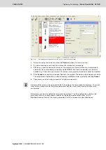
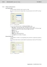
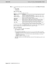
You can make the following settings in the
Ethernet interface setup
group:
•
IP address
: Assigned by the network administrator; identifies the participant in the data exchange.
•
Subnet mask
: Assigned by the network administrator; contains information on the network
configuration (address range).
•
Host name:
Name by which the Ethernet participant (here the compact system/the KE of the
tightening system) can be addressed.
•
DNS:
Assignment of logical participant names to unique IP addresses.
•
Domain name
: The domain name is the same for all the participants in an Ethernet, the full logical
name of a participant is
Hostname@Domainname
.
•
Gateway
: Establishes the external connection.
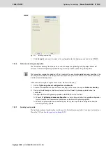
Click
Accept
to store these data in the program.
Click
Accept
to store the data in the program.
7.5.2.5
Setting up additional interfaces
Type A interface modules
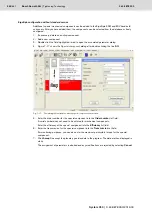
This interface is intended for inserting type A interface modules from Rexroth. A tightening system is
controlled by this interface.
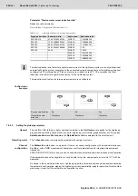
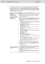
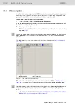
Open the associated parameter dialog by double clicking the parameter field in line A (see Figure
).
In the
Select interface module
field, select the desired module from the drop-down list and set its
parameters.
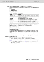
General parameters for all interfaces
Physical interface
The physical characteristics of the interface depend on the field bus module used. They can only be
partially configured via the operating system.
Number of I points /
Number of O points
This parameter determines how many control signals should be processed via the field bus interface.
Receive data / Send
data
Setting of the remaining data width. These settings depend on the set scope of the I/O points. If the
maximum available bandwidths are exceeded, the settings will be automatically corrected to correspond
to the maximum data width. Make sure that the receipt range for ID codes is also set here.
The allocation of the data buffer is shown in tables in section
Layout of the data buffer for transferring
.
Receive IL data /
Send IL data
Only with KE350G IL and CS351x-IL: Setting of the remaining data width. These settings depend on the
set scope of the I/O points. If the maximum available bandwidths are exceeded, the settings will be
automatically corrected to correspond to the maximum data width.
Detailed information on the data exchange via Ethernet can be found under
!
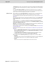
This setting only reserves the memory space for the logical control signals (1 bit per input or output).
Control signal assignment is implemented using the PLC assignment table.
The indicated value ranges are maximum values that can only be fully used if the other parameters have
not been set to the maximum value.
Summary of Contents for Rexroth Tightening System 350
Page 4: ...4 641 Bosch Rexroth AG Schraubtechnik System 350 3 608 878 300 2019 03 ...
Page 120: ...120 641 Bosch Rexroth AG Tightening Technology 3 608 878 300 System 350 3 608 878 300 2019 03 ...
Page 194: ...194 641 Bosch Rexroth AG Tightening Technology 3 608 878 300 System 350 3 608 878 300 2019 03 ...
Page 638: ...638 641 Bosch Rexroth AG Tightening Technology 3 608 878 300 System 350 3 608 878 300 2019 03 ...

