background image

Company Registered in England No: 4167649    VAT Registration No: 732 5692 25    BS EN ISO 9001:2008 No: LRQ 0964389

+44 (0)1204 699 959

enquiries@hyquip.co.uk

Hyquip Limited   New Brunswick Street   Horwich   Bolton   Lancashire   BL6 7JB   UK

www.hyquip.co.uk

/web/index

RE 30523-B/09.13  |  Installation and operation 

Hydraulics

  |  Bosch Rexroth AG  

13/48 

Installing the VSPD 2 


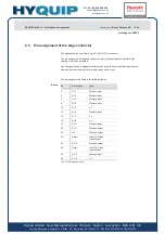
2.5  Pin assignment of the edge connector 

The edge connector is a 64-pin, type G (DIN 41612) connector. 

The pin assignment of the edge connector  is not fully downward compatible  with 
existing, older valve amplifiers. 

Any changes in the pin assignment were made so as to ensure that damage is avoid-
ed when an older controller card is replaced by a newer one. 


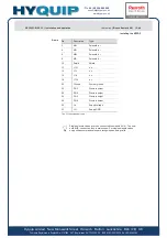
The pin assignment is listed in the following tables. 

Pin


Description


Type


DI 1 

Discrete input 

DI 2 

Discrete input 

DI 3 

Discrete input 

DI 4 

Discrete input 

10 

DI 5 

n. c. 

12 

DI 6 

Discrete input 

14 

DI 7 

n. c. 

16 

DI 8 

n. c. 

18 

DI 9 

Discrete input 

20 

DO 1 

Discrete output 

22 OK 

Discrete 

output 

24 Data 

+  Local CAN Bus  

Input/Output 

26 

DO 2 

Discrete output 

28 Data 

–  Local CAN Bus  

Input/Output 

30 

AO 1 

Analog output 

32 

AO 2 

n. c. 

Tab. 1 Pin assignment row d 


Row d 

Summary of Contents for Rexroth VT-VSPD Series

Page 1: ...9 44 0 1204 699959 enquiries hyquip co uk Hyquip Limited New Brunswick Street Horwich Bolton Lancashire BL6 7JB UK www hyquip co uk web index The Drive Control Company VT VSPD Digital valve amplifier for proportional valves without position feedback Installation and operation RE 30523 B 09 13 Replaces 08 07 ...

Page 2: ...732 5692 25 BS EN ISO 9001 2008 No LRQ 0964389 44 0 1204 699959 enquiries hyquip co uk Hyquip Limited New Brunswick Street Horwich Bolton Lancashire BL6 7JB UK www hyquip co uk web index 2 48 Bosch Rexroth AG Hydraulics Installation and operation RE 30523 B 09 13 ...

Page 3: ...pply 6 1 3 Preconditions for operation 7 2 Installing the VSPD 8 2 1 Safety regulations 8 Use in accordance with the intended purpose 9 Personnel Selection and Qualification 9 Design Changes and Electrical Installation 9 2 2 Repair and Troubleshooting 10 2 3 Transport Storage and Handling the Controller Card 11 2 4 Installing the card 12 2 5 Pin assignment of the edge connector 13 2 6 Installation...

Page 4: ...xroth AG Hydraulics Installation and operation RE 30523 B 09 13 4 1 Display input keys and connections of the controller card 21 4 2 Diagnostics test jacks 23 4 3 Menu Tree for Setup and Parameters Option Display 23 4 4 Display Input Key Operations Option Display 35 5 Carrying out diagnoses 40 5 1 Diagnostic options on the VSPD controller card 40 5 2 Diagnostics options by means of BODAC 41 6 Faul...

Page 5: ...installation and oper ation of the controller card Observing these instructions helps to avoid risks reduce repair costs and downtimes increase the service life and reliability of the controller card Additionally please observe all regulations that are in effect in the country and or community to prevent accidents and to protect the environment These instructions only describe the installation and...

Page 6: ...ips for optimal use of the controller card Special safety notes are provided at the relevant locations These are indicated by the following symbols General hazard This sign is placed in front of activities which represent a potential hazard to persons and or extensive damage to equipment If the source of the hazard can be exactly defined the corresponding pictogram is used Hazard of electric power...

Page 7: ...23 B 09 13 Installation and operation Hydraulics Bosch Rexroth AG 7 48 General 1 1 3 Preconditions for operation The controller card is operated in an open card holder VT3002 2x 48F or VT 3002 2x 64G according to RE 29 928 The open card holder must be installed in a control cabinet since there is no shock hazard protection provided When no voltage supply is provided from the system side you can al...

Page 8: ...heless its use can result in personal injury and damage to property when You operate the VSPD controller card not in accordance with the intended pur pose see page 9 Use in accordance with the intended purpose The VSPD controller card is not installed commissioned and operated by special ist personnel You modify or convert the VSPD controller card improperly You do not observe the safety regulatio...

Page 9: ...ith the installation startup and operation of the VSPD controller card and with all the warning notes and safety regu lations contained in the accompanying documentation Work on the electrical equipment must be performed only by qualified special ists or by personnel appropriately instructed and under the supervision and guidance of persons qualified and familiar with electrical safety standards A...

Page 10: ...and power supply lines Noise is bypassed only if the system ground does not couple noise into the controller card Rexroth also recommends shielding solenoid wiring Do not use logical signals from the controller card IE OK signal for switching machine safety circuits see European Norm Safety Requirements for Fluid Power Systems and Com ponents EN982 1996 2 2 Repair and Troubleshooting If the contro...

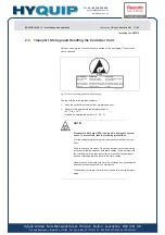
Page 11: ...HACD_HW_DE_2 1 Fig 1 Notes for handling printed on the packaging Comply with the following requirements Keep the controller card away from moisture and dust Adhere to the permissible temperature range of 20 C to 70 C allowable operating temperature 0 50 C ______________________________________________________________ NOTE Electrostatic discharge ESD can result in damage to compo nents To prevent t...

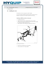
Page 12: ...ll the controller card as shown in Fig 2 Installing the controller card in the card holder provided for this purposes Installing the VSPD controller card correctly De energize the rack used Hold the controller card by the front panel and take it out of the packing Slide the controller card into the guard rails of the rack as shown in Fig Installing the controller card without using excessive force...

Page 13: ...dge connector is not fully downward compatible with existing older valve amplifiers Any changes in the pin assignment were made so as to ensure that damage is avoid ed when an older controller card is replaced by a newer one The pin assignment is listed in the following tables Pin Description Type 2 DI 1 Discrete input 4 DI 2 Discrete input 6 DI 3 Discrete input 8 DI 4 Discrete input 10 DI 5 n c 1...

Page 14: ...draulics Installation and operation RE 30523 B 09 13 2 Installing the VSPD Pin Description Type 2 AI3 n c 4 AI3 n c 6 AI2 Differential input 8 AI2 Differential input 10 AI1 n c 12 AI1 n c 14 AI4 Differential input 16 AI4 Differential input 18 AI5 Differential input 20 AI5 Differential input 22 AI6 Differential input 24 AI6 Differential input 26 AO3 Analog Output 28 AGND Analog GND 30 REF Reference...

Page 15: ...the VSPD 2 Pin Description Type 2 MA Solenoid a 4 MA Solenoid a 6 MB Solenoid b 8 MB Solenoid b 10 Shield Shield 12 L1O n c 14 L1I n c 16 L1I n c 18 L1O n c 20 Ground System ground 22 DO 3 Discrete output 24 DO 4 Discrete output 26 DO 5 Discrete output 28 DO 6 Discrete output 30 UB Supply voltage 32 LO Supply GND Tab 3 Pin assignment row z Single solenoid valves are to be connected to solenoid A A...

Page 16: ...ire BL6 7JB UK www hyquip co uk web index 16 48 Bosch Rexroth AG Hydraulics Installation and operation RE 30523 B 09 13 2 Installing the VSPD Pin Description Type 2 DO 7 n c 4 SSI Clk n c 6 SSI Clk n c 8 SSI Data INC Ua1 n c 10 SSI Data INC Ua1 n c 12 Ua2 n c 14 Ua2 n c 16 Ua0 n c 18 Ua0 n c 20 L2O n c 22 L2I n c 24 L2I n c 26 L2O n c 28 GND_CAN n c 30 CANL n c 32 CANH n c Tab 4 Pin assignment row...

Page 17: ...tion Local Bus The local bus is used to connect the individual amplifier cards of the HACD family Up to 32 cards can be connected Each amplifier must be assigned a clear bus ad dress The connection is established using a CAN protocol with a baud rate of 250kbit The maximum length of the most distant amplifier cards must not exceed 280m Moreover the maximum length of the branch lines of 1 m must be...

Page 18: ...troller cards 3 1 Providing readiness for operation The procedure of commissioning the VSPD controller card depends on various factors on site For this reason only basic commissioning steps can be described in these instructions Making the controller card ready for operation Carefully check cabling Apply voltage to the VSPD controller card Fig 4 Front panel of the VSPD controller card 9 The contro...

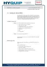
Page 19: ...s and program windows of the software are matched to your controller card This makes the operation of the software very easy Installation requirements 100 IBM compatible PC with the following minimum requirements 200 MHz Pentium processor or comparable 32 MB working memory RAM VGA graphic card minimum resolution 800x600 pixels Hard drive with minimum 2 MB available space CD ROM drive Mouse Free se...

Page 20: ...r operation as described in chapter 2 4 Installing the card you can start with commissioning Before starting the next steps make sure that the following requirements are met Serial interface cable 1 1 cable available Free serial interface available on the PC Software BODAC is installed Proceeding for initial startup Connect serial interface cable mat no R900776897 to the port of the VSPD controlle...

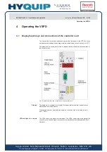
Page 21: ...el of the VSPD to check parameters and settings attach diagnostic instruments and connect the card to a PC The graphic below shows an overview of display control elements and connections of the controller card Fig 5 Display input keys and connections of the controller card The display is four characters in length Messages that exceed four characters are displayed as a scrolling display When parame...

Page 22: ...aulics Installation and operation RE 30523 B 09 13 4 Operating the VSPD The serial interface on the front panel is designed as nine pin D sub socket according to the RS 232 standard Establish the connection to the serial interface of the PC with a serial data cable Four buttons are located on the front panel of the card The functions of these buttons are described in detail in section 4 4 Display ...

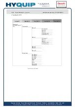
Page 23: ... Menu Tree for Setup and Parameters Option Display The following contains an overview of the menus that can be selected using the but tons on the HACD controller card Shown are the parameters and settings that are available An overview of the items listed below are shown on the following pages Menu tree Parameter Menu tree Setup Menu tree Valve menu Part 1 Menu tree Valve menu Part 2 Menu tree Str...

Page 24: ... web index 24 48 Bosch Rexroth AG Hydraulics Installation and operation RE 30523 B 09 13 4 Operating the VSPD Fig 6 Menu tree Parameter Level 1 Level 2 Level 3 Level 4 Level 5 Parameter Use ENTER to go to menu Commands Binary0 Command0 Ramp0 Ramp0 S ramp 0 start S ramp 0 end Binary1 Command1 Ramp1 Ramp1 S ramp 1 start S ramp 1 end Binary2 Binary4 Binary15 Motion data Ext Ramp Ext Ramp Ext CMD Int ...

Page 25: ...B 09 13 Installation and operation Hydraulics Bosch Rexroth AG 25 48 Operating the VSPD 4 Fig 7 Menu tree Setup There has to be an obligatory reinitialization of the controller card after changing a bus ID Please toggle the card when the changes are written successfully to the memory Level 1 Level 2 Level 3 Level 4 Level 5 Setup Press ENTER ESC Language to go to the configuration menu English Germ...

Page 26: ...Hydraulics Installation and operation RE 30523 B 09 13 4 Operating the VSPD Fig 8 Menu tree Valve menu Part 1 Level 1 Level 2 Level 3 Level 4 Level 5 Valve Menu Press ENTER ESC Off to go to the configuration menu Valve o l 4WRA NG6 2x NG10 2x 4WRZ NG10 5x NG16 6x NG25 5x NG32 5x NG52 5x NG10 7x NG16 7x NG25 7x NG32 7x NG52 7x 3DREP NG6 1x NG6 2x DBEP NG6 1x DBE M T NG6 5x DBET NG6 6x Z DBE NG6 1x ...

Page 27: ...30523 B 09 13 Installation and operation Hydraulics Bosch Rexroth AG 27 48 Operating the VSPD 4 Fig 9 Menu tree Valve menu Part 2 Fig 10 Menu tree Structure Level 1 Level 2 Level 3 Level 4 Level 5 DRE M NG10 5x NG25 5x NG32 4x 3DRE M NG10 5x NG16 5x NG10 6x NG16 6x User1 User2 Level 1 Level 2 Level 3 Level 4 Level 5 Structure Press ENTER ESC Ext CMD to go to the configuration menu Type Off Voltage...

Page 28: ...ion and operation RE 30523 B 09 13 4 Operating the VSPD Fig 11 Menu tree Command Adjust Part 1 Level 1 Level 2 Level 3 Level 4 Level 5 Command Adjust Press ENTER ESC Overlap to go to the configura tion menu Deadband 0 0 100 0 Step 0 0 100 0 Step 0 0 100 0 Offset 100 00 100 00 Limit Limit 0 0 100 0 Limit 0 0 100 0 Current Curve User 1 Precurrent 0 3000 mA Jump Current 0 3000 mA Max Current 0 3000 m...

Page 29: ...ip Limited New Brunswick Street Horwich Bolton Lancashire BL6 7JB UK www hyquip co uk web index RE 30523 B 09 13 Installation and operation Hydraulics Bosch Rexroth AG 29 48 Operating the VSPD 4 Fig 12 Menu tree Command Adjust Part 2 Level 1 Level 2 Level 3 Level 4 Level 5 Dither Frequency 0 1000 Hz Amplitude 0 600 mA Miscellaneous Solenoids 2 A B 1 A ...

Page 30: ... Analog I O Part 1 Level 1 Level 2 Level 3 Level 4 Level 5 Analog I O Press ENTER ESC Inputs to go to the configura tion menu Voltage b14 b16 Type 10 Volts 0 10 Volts Range 100 0 100 Min Value V 11 00 11 00 V Max Value V 11 00 11 00 V Min Fault V 11 0 11 0 V Max Fault V 11 0 11 0 V Max Unit 100 0 s Current b22 b24 Type 4 20 mA Range 100 0 100 Min Value mA 2 00 22 00 mA Max Value mA 2 00 22 00 mA M...

Page 31: ...Menu tree Analog I O Part 2 Level 1 Level 2 Level 3 Level 4 Level 5 Max Value V 11 00 11 00 V Max Value mA 2 00 22 00 mA Min Fault V 11 0 11 0 V Min Fault mA 2 0 22 0 mA Max Fault V 11 0 11 0 V Max Fault mA 2 0 22 0 mA Max Unit 0 0 300 0 s Ramp b18 b20 Type 0 10 Volt 4 20 mA Range 0 100 Min Value V 11 00 11 00 V Min Value mA 2 00 22 00 mA Max Value V 11 00 11 00 V Max Value mA 2 00 22 00 mA Min Fa...

Page 32: ...g the VSPD Fig 15 Menu tree Digital I O Part 1 Level 1 Level 2 Level 3 Level 4 Level 5 Digital I O Press ENTER ESC Inputs to go to the configura tion menu Enable Set OK Off On Outputs DO1 Type Sol A active DO1 Window 100 00 100 00 DO1 Debounce 0 01 60 00 DO1 zero active Off On DO2 Type Sol B active DO2 Window 100 00 100 00 DO2 Debounce 0 01 60 00 DO2 zero active Off On DO3 Type Off Sol B active So...

Page 33: ...tree Digital I O Part 2 Level 1 Level 2 Level 3 Level 4 Level 5 DO4 Type Off Sol B active Sol A active Ramp done Error analog I O ABS actual WIN FAULT STATUS DO4 Window 100 00 100 00 DO4 Debounce 0 01 60 00 DO4 zero active Off On DO5 Type Off Sol B active Sol A active Ramp done Error analog I O ABS actual WIN FAULT STATUS DO5 Window 100 00 100 00 DO5 Debounce 0 01 60 00 DO5 zero active Off On DO6 ...

Page 34: ...ion and operation RE 30523 B 09 13 4 Operating the VSPD Fig 17 Menu tree Faults Level 1 Level 2 Level 3 Level 4 Level 5 Faults Press ENTER ESC Voltage to go to the configura tion menu b14 b16 Type Off Stop Flag Debounce 0 01 60 00 Current b22 b24 Type Off Stop Flag Debounce 0 01 60 00 Ramp b6 b8 Type Off Stop Flag Debounce 0 01 60 00 Ramp b18 b20 Type Off Stop Flag Debounce 0 01 60 00 short circ s...

Page 35: ...ee section 4 3 Menu Tree for Setup and Parameters Pressing the DOWN key moves in the downward direction within the selected level to available menu items for an overview see section 4 3 Menu Tree for Setup and Parameters Change menu mode Parameterization Menu Press the ENTER key for 2 seconds or longer to switch to configuration mode EDIT Parameters Change menu level Press the ENTER key to take yo...

Page 36: ...n configuration mode Changing from Run Mode to Configuration Mode EDIT Param eters The card must be in run mode The display will show scrolling text to display the manufacturer s name the software version for the controller or a custom configured text string Press and hold Enter and ESCAPE simultaneously for at least 2 seconds except when in EDIT Parameter mode see above until the display reads Se...

Page 37: ...cally return to successively higher menu levels until Run Mode is reached The VSPD Control Card is fully operational in Configuration Mode To change a parameter using the input keys As an example the parameter Max Value see Fig 13 Menu tree Analog I O Part 1 Inputs AI1 is shown In this case set the parameter to 10 Volts The card is now in Run Mode The display will show scrolling text to display th...

Page 38: ... select Analog I O Press ENTER 9 The card is now at the second level of the Configuration Menu Analog I O mode Press the UP or DOWN keys to select Inputs Press ENTER 9 The menu entry Analog Input Voltage is shown Press ENTER Press the UP or DOWN keys to select Max Value Press ENTER 9 The current value is shown Press UP This creates a positive sign Pressing DOWN gives the value a negative sign Pres...

Page 39: ...OUT1 see Fig 7 Menu tree Setup will be used The card should be in Run Mode The display will show scrolling text to display the manufacturer s name the software version for the controller or a custom configured text string Press and hold the ENTER and ESCAPE keys for at least 2 seconds until the display reads Setup 9 The card is now in Configuration Mode Press ENTER 9 The card is at the second leve...

Page 40: ...nal of analog output AO3 The solenoid current of the valve can be measured at this output In contrast to AO3 you can select the signal to be measured The signal is selected in the program BODAC With the factory setting the signal ramped command val ue is selected During initial startup BODAC software can be used to select the action of the control ler when an error occurs available in the Error sc...

Page 41: ...al detailed diagnostics options The process data window and the status window give an overview of the current state of the controller card The process data window shows the current signal processing of the controller card This provides a quick overview of the current state of process data The status window allows an evaluation of the signals currently present They are classified by the status word...

Page 42: ...The level at analog input AI2 is outside the valid signal range adjustable see Fig 17 Menu tree Faults Analog input AI4 command value U The level at analog input AI4 is outside the valid signal range adjustable see Fig 17 Menu tree Faults Analog input AI5 ramp The level at analog input AI5 is outside the valid signal range adjustable see Fig 17 Menu tree Faults Analog input AI6 command value I The...

Page 43: ...__________ NOTE The fuse is defective and must be replaced The fuse has opened due to mechanical damage or a product de fect In this case replace the fuse with a new one of the type indicated above The fuse has opened due to external influences i e due to compo nents connected to the controller card In such cases diagnose and correct the problem that caused the fuse to open Only then replace the f...

Page 44: ...k Street Horwich Bolton Lancashire BL6 7JB UK www hyquip co uk web index 44 48 Bosch Rexroth AG Hydraulics Installation and operation RE 30523 B 09 13 6 Faults HACD_HW_DE_6 2 Fig 19 Fuse on the VSPD controller card Use a suitable test device to check the fuse continuity test If the fuse is defective replace it with the same type Re fit the VSPD and carry out a function test ...

Page 45: ...d Installation 12 Diagnostic terminal 40 Diagnostics options by means of BODAC 41 diagnostics port 23 Differential inputs 10 Digital input 13 Display 21 DOWN 35 Drives electromechanical and electrohydraulic 5 EC Directive 89 392 EEC Machinery Directive 8 Edge connector 13 EMC regulations 8 ENTER 35 Error conditions 40 Error messages 42 ESCAPE 35 Front 12 Fuse 43 Handling 11 Initial startup 40 Inst...

Page 46: ...RE 30523 B 09 13 7 Index Valve menu Part 1 26 Valve menu Part 2 27 Noise sources 9 operation 7 Parameter changing 37 Power cables 9 Reference voltage 14 Resultatssymbol 6 Run mode 36 Running text 36 37 39 Safety regulations 5 Sensor lines 9 Serial interface 22 Shield 10 Shielding 10 Signs 6 Software BODAC 19 Supply GND 15 Supply voltage 15 Symbols 6 System ground 10 Tätigkeitssymbol 6 Troubleshoot...

Page 47: ...692 25 BS EN ISO 9001 2008 No LRQ 0964389 44 0 1204 699959 enquiries hyquip co uk Hyquip Limited New Brunswick Street Horwich Bolton Lancashire BL6 7JB UK www hyquip co uk web index RE 30523 B 09 13 Installation and operation Hydraulics Bosch Rexroth AG 47 48 Index 7 ...

Page 48: ... the ex clusive property of Bosch Rexroth AG It may not be reproduced or given to third parties without its consent The data specified above only serve to describe the product No statements concerning a certain condition or suitability for a certain application can be derived from our information The information giv en does notrelease the user from the obligation of own judgment and verification I...

Reviews: