Hydraulics training system WS290 | RE 00225-B/12.15
Bosch Rexroth AG 35/104
Information on this product
5.10.2
Assemblies and functions
The oil tank has a volume of 40 liters. Oil is filled in through a filling and breathing
filter at the top of the oil tank.
The oil tank comprises the following assemblies:
Filling/breathing cap
Inspection glass
Thermometer
Oil drain plug
The oil drain plug G1/2 fastened at the side of the oil tank is used to empty
the oil tank. Before opening of the oil drain plug, the power unit is to
be decommissioned.
By means of the visual filling level indicator (inspection glass), you can visually
check the filling level. If the system is switched off (i.e. the pump is not running)
and the oil level is between the two "Max." and "Min." marks, the filling level is ok.
The thermometer is integrated in the inspection glass and measures the oil
temperature on a permanent basis.
The oil tank is filled and bled via the filling and breathing filter which prevents dirt
from getting into the oil during the air exchange. The oil tank is filled with oil
through the connection of the filling and breathing filter. To this end, the filter cap
must be screwed off.
A three-phase current motor drives two vane pumps with zero stroke control
which suck in the hydraulic oil from the oil tank and generate the required
system pressure p. The vane pump has been set at the factory to a standby
pressure of 15 bar.
The hose lines serve as connection between the individual components of the
hydraulic power unit.
The sealed pressure relief valves secure the pump circuit with 70 bar.
The check valves block the flow in the one direction and open against a spring
in the other direction. In this connection, the spring force corresponds to a
certain pressure.
During operation, the oil flows via the check valves to the LS control block.
However, it blocks the flow from the LS control block to the vane pump.
The return flow of the oil from the P/T distributors of the hydraulic power unit to
the oil tank is effected via the "T" port and the inline filter (3.0) with optical
clogging indicator.
The filter with bypass circuit is used to filter out smallest contamination from the
hydraulic oil. The filter consisting of the filter housing with a filter element (20 µm)
filters the hydraulic fluid to the tank.
If the filter element is contaminated and has to be exchanged, this is visually
displayed by the clogging indicator.
The voltage supply of the hydraulic power unit is effected via the control box at
the hydraulic power unit. The control box with protective motor switch is
connected to the control box at the base frame of the WS290 training system by
means of a coded connector.
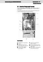
1.0 Oil tank
1.1 Oil level and temperature display
1.2 Filling and breathing filters
2. Motor-pump unit
2.0 Three-phase current motor
2.1 Vane pump
2.2//2.31/2.4/2.51 Hose line
2.32/2.52 Pressure relief valve
2.6/2.7 Check valve
3.0 Return flow filter
3.1 Clogging indicator optical
Control box
consisting of 5.0
switch housing
and
5.2 power switch


