48/104 Bosch Rexroth AG
Hydraulics training system WS290 | RE 00225-B/2.15
Operating and display elements
7.2
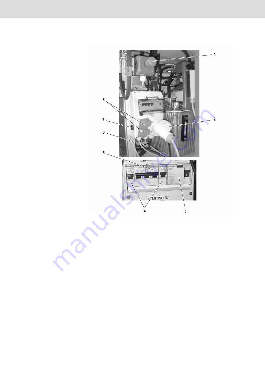
Operating elements at the control box
Fig. 28:
Operating elements at the control box
1
EMERGENCY OFF pushbutton
2
Coded socket
3
FI circuit breaker (optional)
4
Automatic circuit breakers
for socket
5
Automatic circuit breakers for
coded socket
6
Connection cable with connector
7
"Start" pushbutton
8
230 V socket
The current connection to the control box of the hydraulic power unit is effected
via a coded connector connection.
The circuit breaker serves as residual current safeguard and interrupts the current
supply to the control box in case of a residual current; the switch is set to "0".
"0" position = current supply interrupted
"1" position = current supply is available
Remedy the cause of the triggering of the FI circuit breaker first before resetting
the switch at the FI circuit breaker to "1".
2. Coded socket
3. FI circuit breaker (optional)


