52/104 Bosch Rexroth AG
Hydraulics training system WS290 | RE 00225-B/2.15
Operating and display elements
7.5
Load-sensing control block (LS control block)
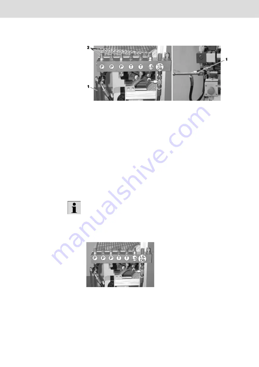
Fig. 32:
LS control block with 3/2-way ball valve and LS pressure relief valve
1
Switching lever for rest/
operating position
2
Hose couplings for exercise
set-ups
The LS control block allows for a pump start-up with 15 bar.
This start-up is easily possible by operation of the 3/2-way ball valve.
Notice: The marking on the operating square is to be observed!
Vertical position = rest position
Horizontal position = operating position
The 3-way ball valve allows for the depressurized unloading of the system to the
leakage oil with simultaneous blocking to the pump.
At the LS control block, there are hose couplings for the connection of hose lines
for diverse set-ups and functions (see fig. 33):
In the project manuals, the designation connection block is used in order to
avoid any mistake with the control blocks of the exercise set-ups.
3 x hose couplings P (pump) for the operating pressure at exercise set-ups
2 x hose couplings T (tank) for the return flow at exercise set-ups
1 x hose coupling for load-sensing signal
Fig. 33:
LS control block: Hose connections
Hose couplings


