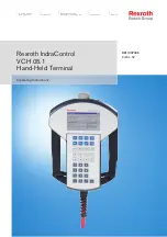
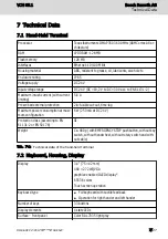
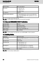
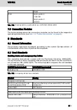
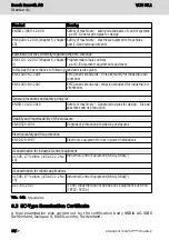
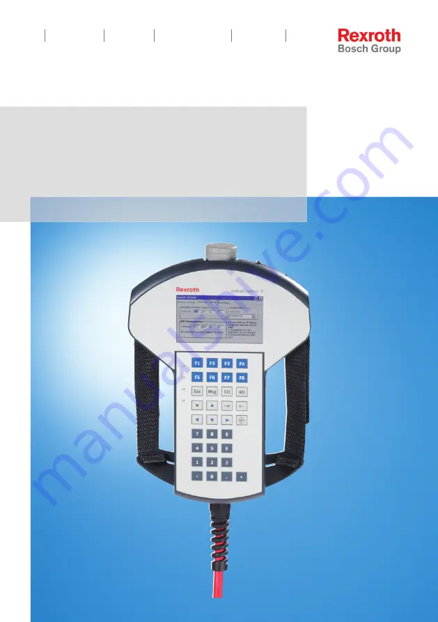
background image

Operating Instructions

Electric Drives

and Controls 

Pneumatics

Service

Linear Motion and 

Assembly Technologies

Hydraulics

Rexroth IndraControl

VCH 05.1

Hand-Held Terminal

R911337305

Edition 02

Summary of Contents for Rextop IndraControl VCH 05.1

Page 1: ...Operating Instructions Electric Drives and Controls Pneumatics Service Linear Motion and Assembly Technologies Hydraulics Rexroth IndraControl VCH 05 1 Hand Held Terminal R911337305 Edition 02 ...

Page 2: ...roth AG It may not be repro duced or given to third parties without its consent Liability The specified data is intended for product description purposes only and shall not be deemed to be a guaranteed characteristic unless expressly stipulated in the contract All rights are reserved with respect to the content of this docu mentation and the availability of the product Editorial Department Develop...

Page 3: ... Ambient Conditions 6 7 Technical Data 7 7 1 Hand Held Terminal 7 7 2 Keyboard Housing Display 7 7 3 Stop and EMERGENCY STOP Pushbutton 8 7 4 Enabling Button 8 7 5 Connection Modules 9 8 Standards 9 8 1 General Information 9 8 2 Used Standards 9 8 3 EC Type Examination Certificate 10 8 4 CE Marking 11 8 4 1 Declaration of Conformity 11 8 5 UL CSA Certified 11 9 Interfaces 12 10 Assembly Disassembl...

Page 4: ...3 Error Causes and Elimination 18 14 Maintenance 18 14 1 General Information 18 14 2 Regular Maintenance Tasks 18 14 3 Display 19 14 4 Maintenance 19 14 5 Updating the Operating System 19 15 Ordering Information 20 15 1 Accessories and Spare Parts 20 15 2 Type Code 21 16 Disposal 21 16 1 General Information 21 16 2 Take Back 22 16 3 Packaging 22 16 4 Batteries and Accumulators 22 17 Service and Su...

Page 5: ...mbly installation Programmer Mechanic electrician To dismount To dispose Commissioning engineer Technologist Process specialist Maintenance technician Fig 1 1 Assigning the present documentation to the target groups product phases and ac tivities of the target group Purpose This document instructs the technical staff of the machine manufacturer on how to perform the mechanic and electrical install...

Page 6: ...m or the component e g MLC IndraLogic MTX MLC XLC or IndraLogic component Customer feedback Customer requests comments or suggestions for improvement are of great im portance to us Please email your feedback on the documentations to Feed back Documentation boschrexroth de Directly insert comments in the elec tronic PDF document and send the PDF file to Bosch Rexroth 2 Product Identification and Sc...

Page 7: ...arcode Serial number Part number as bar code Part number Type code type designation code Company name Fig 2 1 Type plate 2 2 Scope of Delivery Hand Held Terminal Connecting cable Safety instructions The scope of delivery depends on the customer configuration 3 Using the Safety Instructions 3 1 Safety Instructions Structure The safety instructions are structured as follows VCH 05 1 Bosch Rexroth AG...

Page 8: ...ttention to the safety instruction and signifies the degree of danger The safety alert symbol a triangle with an exclamation point which precedes the signal words danger warning and caution is used to alert the reader to per sonal injury hazards DANGER In case of non compliance with this safety instruction death or serious injury will occur WARNING In case of non compliance with this safety instru...

Page 9: ...me applies to cables and lines Operation must only be carried out with the hardware component configura tions and combinations that are expressly specified and with the software and firmware indicated and specified in the respective documentation and function al descriptions Typical fields of use of the hand held terminals are Handling systems and assembly systems Packaging and food processing mac...

Page 10: ...o EN 61131 2 Up to 3000 m above sea level acc to EN 61131 2 Mechanical strength Maximum vibration 10 Hz f 57 Hz with 0 15 mm 9 Hz f 150 Hz with 2 g Max shock 25 g 11 ms according to IEC 60068 2 27 Tab 6 1 Ambient Conditions The ambient air must not contain acids alkaline solutions corrosive agents salts metal vapours and other electrically conductive con taminants in high concentrations The ambien...

Page 11: ...consumption at maxi mum configuration 6 W 250 mA at DC 24 V Protection class according to EN 61131 2 or EN 50178 III Weight Ca 480 g with EMERGENCY STOP pushbutton without key switch without handwheel without rotary switch and with out cable Tab 7 1 Technical data of the hand held terminal 7 2 Keyboard Housing Display Display 3 4 75 42 mm 480 272 WQVGA graphics enabled OLED display1 65536 colors T...

Page 12: ... contact Maximum current 1000 mA per contact Usage category DC 13 acc to IEC 60947 5 1 IDEC XA series B10d 100 000 Tab 7 3 Technical data of the stop button and the EMERGENCY STOP pushbutton 7 4 Enabling Button Output type Solid state output Nominal voltage DC 24 V voltage tolerance DC 19 2 V to DC 30 V acc to EN 61131 2 Nominal current Max 500 mA Switching cycles Switch position 2 106 Switch posi...

Page 13: ...ructions comply with the Machinery Directive 2006 42 EC The terms used in these operating instructions are derived from the new Machi nery Directive MD 2006 42 EC The following table compares the old standard to the new standard 98 37 EC ancient standard 2006 42 EC new standard Emergency stop EMERGENCY STOP Tab 8 1 Comparing old and new standards Standard Meaning European Union Directives 98 37 EC...

Page 14: ...ciples EN ISO 12100 2010 Safety of machinery General principles for design Risk as sessment and risk reduction Stability and impermeability of the enclosure EN 60529 1991 Degrees of protection provided by enclosures Electrical safety and fire protection EN 50178 1997 Electronic equipment for use in power installations UL examination for industrial control equipment UL 508 17th edition CSA C22 2 No...

Page 15: ...ectromagnetic compatibility 2004 108 EC Conformity with the regulations of the Directive 2006 42 EG is established by the compliance with the following harmonized European standards for the EMERGENCY STOP pushbutton and the stop button as well as the enabling but ton EN ISO 13850 2008 EN 60204 1 2006 Conformity with the Directive 2004 108 EC is established by the compliance with the applicable par...

Page 16: ...iance is to be verified To guarantee an UL CSA compliant operation the following condi tions have to be fulfilled Use only insulated copper wire suitable for at least 60 75 C 9 Interfaces 1 2 3 S1 Main terminal Enabling device and EMERGENCY StOP pushbutton S12 External cabling for options S2 Communication interface Fig 9 1 Interfaces Note the safety instructions and the interface descriptions in t...

Page 17: ...H 05 1 10 2 Cable Installation Opening the cable chamber 1 Place the hand held terminal on an even and clean surface with the display facing downwards e g ESD mat 2 Use a screw driver type six lobe size 10 to open and close the cable chamber VCH 05 1 Bosch Rexroth AG Assembly Disassembly and Electrical Installation DOK SUPPL VCH 05 IT02 EN P 13 27 ...

Page 18: ...tions due to incorrectly closed cable chamber and sporadical loss of degree of protection NOTICE Verify that the seal is clean and intact Ensure that the seal is positioned correctly in the cable chamber Ensure that no cable is crimped Possible malfunctions of the EMERGENCY STOP pushbutton and the enabling button due to in correctly snapped in connectors NOTICE Ensure that the S1 and S2 connectors...

Page 19: ...the plant especially the safety devices are in a correct state Stopping the system due to connecting a hand held terminal with pressed stop but ton or EMERGENCY STOP pushbutton NOTICE Before commissioning the hand held terminal ensure that the stop button or the EMERGENCY STOP pushbutton is not pressed 2 Connect the 17 pin connector to the VAC connection module 3 Set up the hand held terminal and ...

Page 20: ...uch screen 3 4 OLED display PSP resolution 480 272 Membrane keyboard Fig 12 1 Views of the hand held terminal A figure of the connection module can be found in the operating instructions of the connection module VAC30 31 05 see tab 1 1 Further documents on page 2 12 1 2 Connection to the Control Selecting the Connection Modules The hand held terminal is connected to the control via a connection mo...

Page 21: ...ugging a hand held terminal during the operation would immediately set the system to standstill The connection modules depend on the safety components of the hand held ter minal IndraControl VAC 30 2 IndraControl VAC 31 1 IndraControl VAC 05 1 Actuating element stop button EMERGENCY STOP pushbutton For hand held terminals with black gray stop but ton For hand held terminals with red yellow EMER GE...

Page 22: ...ctive replace the device Tab 13 1 Error causes and error elimination 14 Maintenance 14 1 General Information Maintenance work in the device is only permis sible by skilled staff NOTICE If hardware or software components have to be exchanged please contact the Bosch Rexroth Service or ensure that only skilled staff changes the respective components Dissolution of the foil surface as well as the sea...

Page 23: ... handling the hand held terminal has to be cleaned after it has been soiled Use a soft dry and lint free rag for cleaning 14 5 Updating the Operating System The operating system is updated using a micro SD card The image of the ope rating systems can be obtained from Bosch Rexroth Installation instruction 1 Switch off the system the hand held terminal is connected to 2 Backup all available local d...

Page 24: ...supply during the update 15 Ordering Information 15 1 Accessories and Spare Parts For ordering information about accessories and spare parts please refer to chapter 5 Spare Parts Accessories and Wear Parts on page 6 Bosch Rexroth AG Ordering Information VCH 05 1 20 27 DOK SUPPL VCH 05 IT02 EN P ...

Page 25: ...ircuit CS Override handwheel STOP button and enabling device three stage dual circuit DS Override emergency stop button and enabling device three stage dual circuit FS Override handwheel emergency stop button and enabling device three stage dual circuit GS Other design Ethernet control cable 8 m bayonet lock B1 Ethernet control cable 0 5 m bayonet lock B2 Ethernet control cable 8 m E1 Ethernet con...

Page 26: ...s symbol The symbol indicating separate collection for all batteries and accumulators is the crossed out wheeled bin The end user within the EU is legally obligated to return used batteries Outside the validity of the EU Directive 2006 66 EC keep the stipulated directives Used batteries can contain hazardous substances which can harm the environ ment or the people s health when they are improper s...

Page 27: ...service office first For hotline num bers refer to the sales office addresses on the internet Preparing information To be able to help you more quickly and efficiently please have the following in formation ready Detailed description of malfunction and circumstances resulting in the mal function Type plate name of the affected products in particular type codes and serial numbers Your contact data ...

Page 28: ...Bosch Rexroth AG VCH 05 1 24 27 DOK SUPPL VCH 05 IT02 EN P ...

Page 29: ... 2 H Housing dimensions 13 I Intended use 5 Interfaces 12 M Maintenance 18 O Operating system 17 Order information 6 Ordering information 20 P Product identification 2 S Safety alert symbol 4 Safety instructions 3 4 Scope of delivery 3 Selecting the connection modules 16 Settings 15 Signal words 4 Software specific settings 15 Spare parts 6 Standards 9 EMERGENCY STOP push button 9 10 Suggestions 2...

Page 30: ...Use intended 5 V View hand held terminal 16 W Wear parts 6 Bosch Rexroth AG Index VCH 05 1 26 27 DOK SUPPL VCH 05 IT02 EN P ...

Page 31: ...Notes VCH 05 1 Bosch Rexroth AG ...

Page 32: ...UPPL VCH 05 IT02 EN P Bosch Rexroth AG Electric Drives and Controls P O Box 13 57 97803 Lohr Germany Bgm Dr Nebel Str 2 97816 Lohr Germany Tel 49 9352 18 0 Fax 49 9352 18 8400 www boschrexroth com electrics ...

Reviews: