


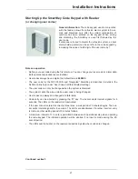
Installation Instructions
11
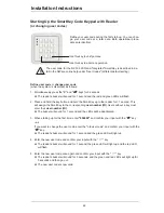
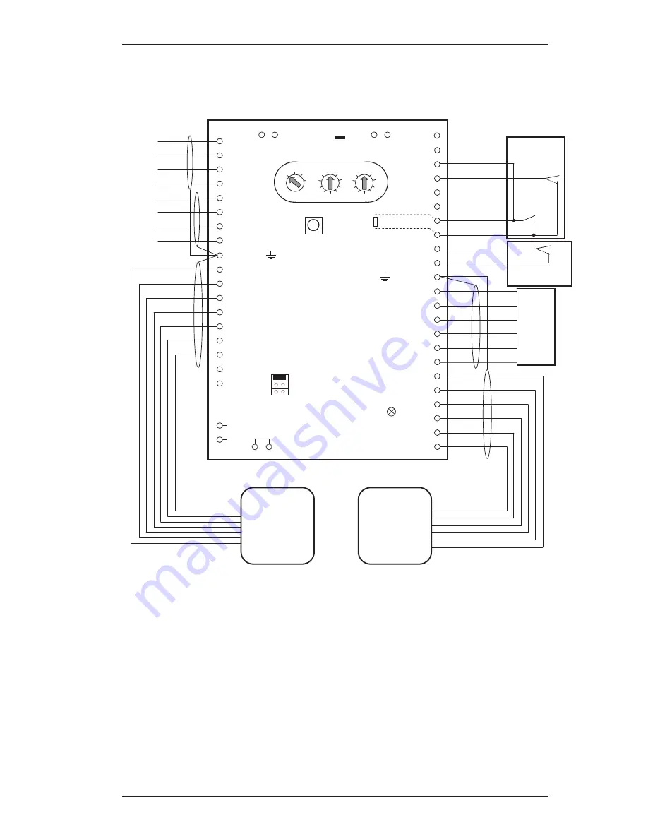
Connecting the Control Panel and Optional Components
Line length <3m
yl
gn
rd
bk
or
bn
SPE
blo-
cking
element
rd
or
yl
gn
bn
bk
Magnetic
contact
Line length <3m
Switch part
Tamper
protection
1
2
3
4
0V 41
LED2 31
DK
10 T7
11 T6
12 T5
13 T4
14 T3
15 T2
16 T1
23 24
PL2 53
0V 52
PL1 51
0V 50
Free 49
Free 48
VÜ 45
0V 44
Ground 43
+12V SPE 42
HALL1 40
HALL2 39
MOT1 38
MOT2 37
ANT1 36
ANT2 35
+12V 34
SU 33
EW1a 47
EW1b 46
LED
1 +U
2 0V
3 aLSN1
4 bLSN1
5 +U
6 0V
7 aLSN2
9 Ground
8 bLSN2
R
E
EG
n
21 Free
22 Free
LED1 32
Free
Free
+
bLSN1
rd
+
0V
aLSN1
0V
aLSN2
bLSN2
bk
wt
yl
rd
bk
wt
yl
LSN
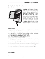
Reader
SmartKey
Code
keypad
Cable length
d
6 m
rd-bl
Bolt contact
bn-gn
gr-pi
wt-gn
gr
bl
wt
17 Test
18
Cable length
d
6 m
R
E
EG 12K1 already installed
n
o
Points 21/22 and 23/24 are connected internally.
o
57 56
Free Free
55 54
Free Free
A
B
C
D
B1 Operation
BR1
B3 Bolt Test
B2 Programming
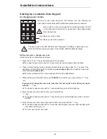
1
0
3
4
5
6
7
8
9
2
CL
0
1
2
1
0
3
4
5
6
7
8
9
2


