Installation Instructions
14
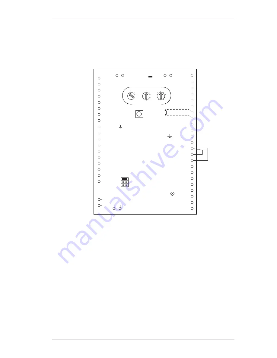
Connecting for Operation Without an SPE Blocking Element
Use the following switching arrangement on the control unit to set the operating mode without
SPE blocking element. Connect the inputs HALL1 and HALL2 to 0V.
0V 41
LED2 31
DK
10 T7
11 T6
12 T5
13 T4
14 T3
15 T2
16 T1
23 24
PL2 53
0V 52
PL1 51
0V 50
Free 49
Free 48
VÜ 45
0V 44
Ground 43
+12V SPE 42
HALL1 40
HALL2 39
MOT1 38
MOT2 37
ANT1 36
ANT2 35
+12V 34
SU 33
EW1a 47
EW1b 46
LED
1 +U
2 0V
3 aLSN1
4 bLSN1
5 +U
6 0V
7 aLSN2
9 Ground
8 bLSN2
R
E
EG
21 Free
22 Free
LED1 32
Free
Free
17 Test
18
57 56
Free Free
55 54
Free Free
A
B
C
D
B1 Operation
BR1
B3 Bolt Test
B2 Programming
1
0
3
4
5
6
7
8
9
2
CL
0
1
2
1
0
3
4
5
6
7
8
9
1




![idatastart OEM-IDS(RS)-BM1-[ADS-BM1]-EN Install Manual preview](http://thumbs.mh-extra.com/thumbs/idatastart/oem-ids-rs-bm1-ads-bm1-en/oem-ids-rs-bm1-ads-bm1-en_install-manual_616031-01.webp)


